Engine Valve Operating System

a technology of operating system and engine valve, which is applied in the direction of valve arrangement, auxilary lubrication, pressure lubrication, etc., can solve the problems of large size of the valve operating system, reduce the space for placing the link arms, and improve the follow-up ability of the valve operating cam

Inactive Publication Date: 2007-12-20
HONDA MOTOR CO LTD
View PDF1 Cites 7 Cited by
  • Summary
  • Abstract
  • Description
  • Claims
  • Application Information

AI Technical Summary

Benefits of technology

[0016] With the arrangement of the first aspect, it is possible to vary the lift amount of the engine valve continuously by displacing the movable shaft continuously. Also, since the one ends of the first and second link arms are turnably connected directly to the rocker arm, it is possible to decrease the space for placing the link arms, thereby reducing the size of the valve operating system. Besides, since the power from the valve operating cam is transmitted directly to the cam-abutting portion of the rocker arm, it is possible to ensure excellent follow-up ability to the valve operating cam. Furthermore, since the first ends of the first and second link arms are turnably connected to the rocker arm via the first and second connecting shafts disposed side by side in a vertical arrangement, and oil is supplied to the upper one of the first and second connecting shafts, the oil which has lubricated between the rocker arm and the upper one of the first and second link arms flows downward to lubricate between the rocker arm and the lower one of the l...

Problems solved by technology

However, in the engine valve operating system disclosed in the above-described Patent Document 1, it is necessary to ensure a comparatively large space to dis...

Method used


Image

  • Engine Valve Operating System
  • Engine Valve Operating System
  • Engine Valve Operating System

Examples


embodiment 1

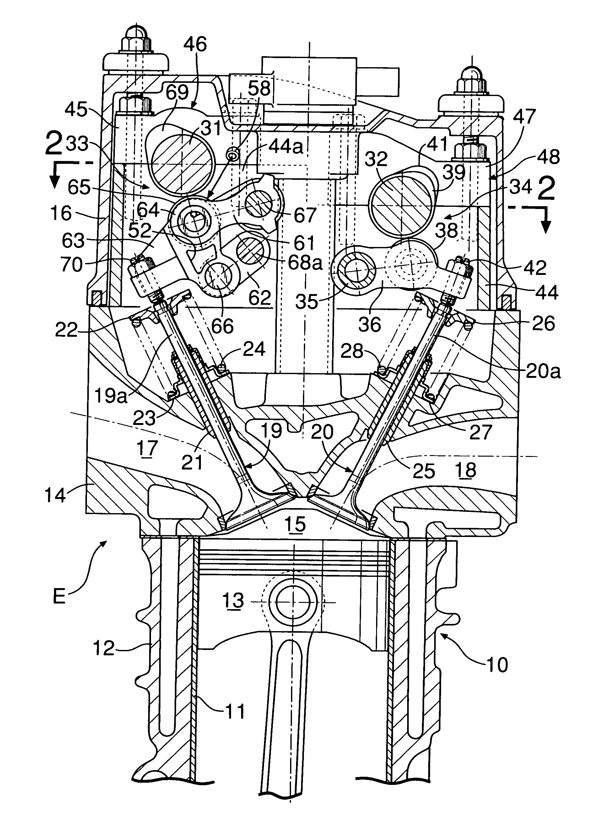
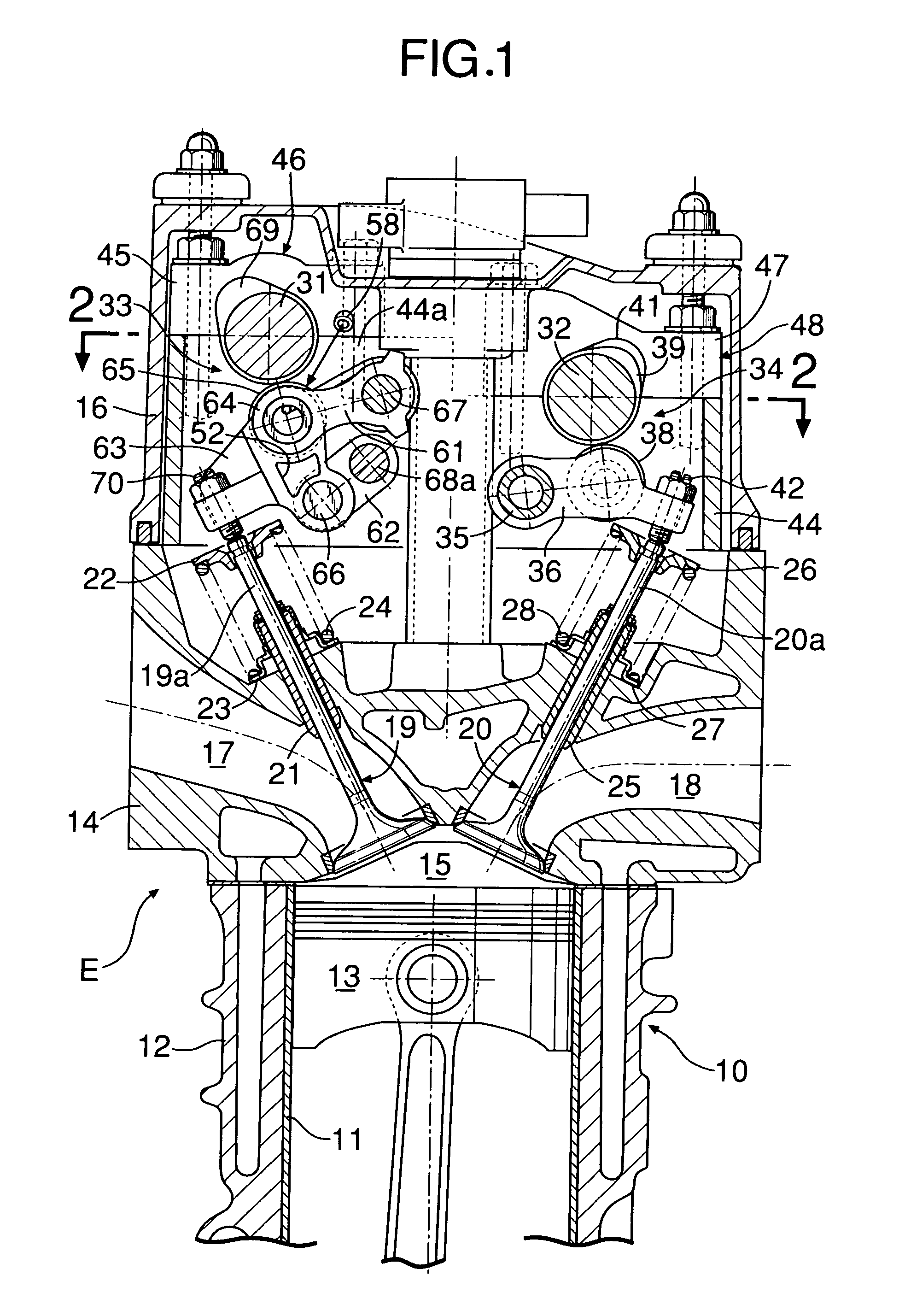
[0054] FIGS. 1 to 11 show a first embodiment of the present invention. First, referring to FIG. 1, an engine body 10 of an in-line multi-cylinder engine E comprises a cylinder block 12 with cylinder bores 11 . . . in the interior, a cylinder head 14 joined to a top face of the cylinder block 12, and a head cover 16 joined to a top face of the cylinder head 14. Pistons 13 . . . are slidably fitted in the cylinder bores 11 . . . . Combustion chambers 15 . . . facing tops of the pistons 13 . . . are formed between the cylinder block 12 and cylinder head 14.

[0055] The cylinder head 14 is equippedwith intake ports 17 . . . and exhaust ports 18 . . . which can be communicated with combustion chambers 15 . . . . The intake ports 17 are opened and closed by a pair of intake valves 19 . . . which are engine valves while the exhaust ports 18 are opened and closed by a pair of exhaust valves 20 . . . . Each intake valve 19 has a stem 19a slidably fitted in a valve guide 21 provided in the cyl...

embodiment 2

[0106]FIG. 12 shows a second embodiment of the present invention. Components corresponding to those in the first embodiment are denoted by the same reference numerals as those in the first example.

[0107] An oil jet 58 serving as oil supply means is fixed to the engine body 10 to supply oil to a first connecting shaft 64 (see the first embodiment) which connects a first end of a first link arm 61 to a second end of a rocker arm 63. According to the second example, the oil jet 58 is installed on a cap 45 on the engine body 10, on one side of the cylinder, with the tip of a pipe 58a placed inside the rim of a combustion chamber 15 when viewed on a projection to a plane orthogonal to the axis of the cylinder (plane parallel to the paper in FIG. 12).

[0108] According to the second embodiment, it is possible to reduce the number of oil jets 58 and supply oil reliably to lubrication points by bringing the tips of the oil jets 58 close to the lubrication points from one side of the cylinde...


PUM


Abstract

An engine valve operating system is provided in which a rocker arm (63) linked and connected to an engine valve (19) and has a cam-abutting portion (65) to abut a valve operating cam (69) is turnably connected, via first and second connecting shafts (64, 66), to one end of a first link arm (61) turnably supported on an engine body (10) and one end of a second link arm (62) turnably supported by a displaceable movable shaft (68a). Also, oil supply means (58) which supply oil to the upper connecting shaft (64) of first and second connecting shafts (64, 66) are fixed to the engine body (10). This makes it possible to implement an engine valve operating system which is compact in size, ensures follow-up ability of the valve opening/closing operation, has a simple lubricating structure with a reduced number of parts, and ensures smooth valve operation while allowing the lift amount of the engine valve to be varied continuously.

Description

TECHNICAL FIELD [0001] The present invention relates to an engine valve operating system equipped with a variable valve lift mechanism which continuously varies the lift amount of an engine valve, namely an intake valve or exhaust valve. BACKGROUND ART [0002] A valve operating system in which one end of a push rod is fitted to one end of a rocker arm having a valve abutment part abutting to an engine valve at the other end side and a link mechanism is provided between the other end of the push rod and a valve operating cam in order to continuously change the amount of lift of the engine valve is already known by Patent Document 1. [0003] However, in the engine valve operating system disclosed in the above-described Patent Document 1, it is necessary to ensure a comparatively large space to dispose a link mechanism and the push rod therein, between the valve operating cam and the rocker arm, and therefore, the valve operating system becomes large in size. In addition, a driving force...

Claims


Application Information

Patent Timeline
IPC IPC(8): F01M1/06F01L1/18F01L13/00F01M1/08F01M9/10
CPCF01L13/0015F01M9/10F01L13/0021
Inventor FUJII, NORIAKINAKAMURA, KATSUNORIYONEKAWA, AKIYUKI
Owner HONDA MOTOR CO LTD
Why Eureka
Try Eureka