Device and Method for Controlling the Flow Speed of a Fluid Flow in a Hydraulic Line

a technology of hydraulic line and fluid flow, which is applied in the direction of process and machine control, combustion air/fuel air treatment, instruments, etc., can solve the problems of powerful wear phenomena of conventional control valves involving this kind of mechanics, and achieve the effect of short switching times

Inactive Publication Date: 2007-12-20
ROBERT BOSCH GMBH
View PDF5 Cites 0 Cited by
  • Summary
  • Abstract
  • Description
  • Claims
  • Application Information

AI Technical Summary

Benefits of technology

[0004] The control device according to the invention with the defining characteristics of claim 1 and the control method according to the invention with the defining characteristics of claim 10 have the advantage over the prior art that no mechanical components are required in order to control the flow speed, i.e. no physically moving components are required. Consequently, the invention functions almost without wear. Moreover, a valve according to the invention does not require any moving parts, permitting implementation of extremely short switching times. This results in clear advantages for the control device and for a hydraulic system equipped with it.
[0005] The present invention is based on the general concept of producing a homogeneous two-phase mixture in a line segment provided for this purpose and setting the respective desired flow speed by varying the mass percentage of the gas phase in the two-phase mixture. In this connection, the invention makes use of the knowledge that within a homogeneous two-phase mixture, the speed of sound depends heavily on the mass percentage of the gas phase so that even very low mass percentages of the gas phase can suffice to significantly reduce the speed of sound of the two-phase mixture. For example, in a mixture of water and water vapor, the speed of sound of approximately 1400 m / s when the mixture contains no gas phase drops to approximately 16 m / s when the mixture contains a gas phase mass percentage of approximately 10−3. Also important for the invention is the consideration that the speed of sound of the two-phase mixture more or less represents the maximum achievable flow speed since supersonic flows result in extremely high shock losses.
[0006] In order to adjust a desired flow speed with the aid of the control device according to the invention, a two-phase mixture is thus intentionally produced in which the mass percentage of the gas phase is selected so that the resulting speed of sound of the two-phase mixture corresponds to the desired flow speed to be set.
[0007] In addition, a control device of this kind can be used in a particularly simple fashion to eliminate or at least smooth pressure pulsations. Because the mass percentage of the gas phase in the two-phase mixture, by means of the resulting speed of sound of the two-phase mixture, defines a maximum permissible flow speed through the line segment of the control device. Subsonic flow speeds can consequently pass through the line segment in a more or less undamped fashion, whereas supersonic flow speeds can be powerfully damped, i.e. significantly smoothed, by the extremely high shock losses. The desired smoothing or elimination occurs because pressure pulses have a locally excessive speed.
[0008] In a suitable fashion, the line segment can have a defined cross-sectional constriction or can itself represent a defined cross-sectional constriction within the hydraulic line. With the aid of such a cross-sectional constriction, it is possible to locally increase the flow speed in the fluid flow in the region of the control device inside the hydraulic line in order to thus more quickly arrive in the range of the speed of sound of the two-phase mixture even at lower flow speeds to the rest of the hydraulic line. It is thus advantageously possible to adapt the control device to the given control range.
[0009] In a modification, the two-phase mixture is suitably produced in the region of the cross-sectional constriction in order to be able to adjust the flow speed independently of the flow direction.
[0010] In another embodiment, the line segment adjoining the cross-sectional constriction can have a two-phase zone with an enlarged cross-section; the two-phase mixture is then produced in the region of this two-phase zone. In an embodiment of this kind, the control of the flow speed depends on the instantaneous flow direction. Initially, the mass content of the gas phase defines the maximum flow speed that can be set. If the two-phase zone is then situated downstream of the cross-sectional constriction, then it is in fact possible to set speeds within the cross-sectional constriction that exceed the speed of sound of the two-phase mixture. But if the two-phase zone is situated upstream of the cross-sectional constriction, then the fluid flow causes the two-phase mixture to also extend into the cross-sectional constriction. Since higher speeds are present there, the speed of sound of the two-phase mixture is reached much, much earlier so that in this flow direction, the control device already exerts its inhibiting or damping action at lower flow speeds in the rest of the hydraulic line. An embodiment of this kind can in particular achieve a direction-dependent reflection of pressure pulsations.
[0011] Other important defining characteristics and advantages of the present invention ensue from the dependent claims, the drawings, and the accompanying description of the figures.

Problems solved by technology

In highly dynamic processes, a conventional control valve involving this kind of mechanics is subjected to powerful wear phenomena.

Method used


Image

  • Device and Method for Controlling the Flow Speed of a Fluid Flow in a Hydraulic Line
  • Device and Method for Controlling the Flow Speed of a Fluid Flow in a Hydraulic Line

Examples


Embodiment Construction

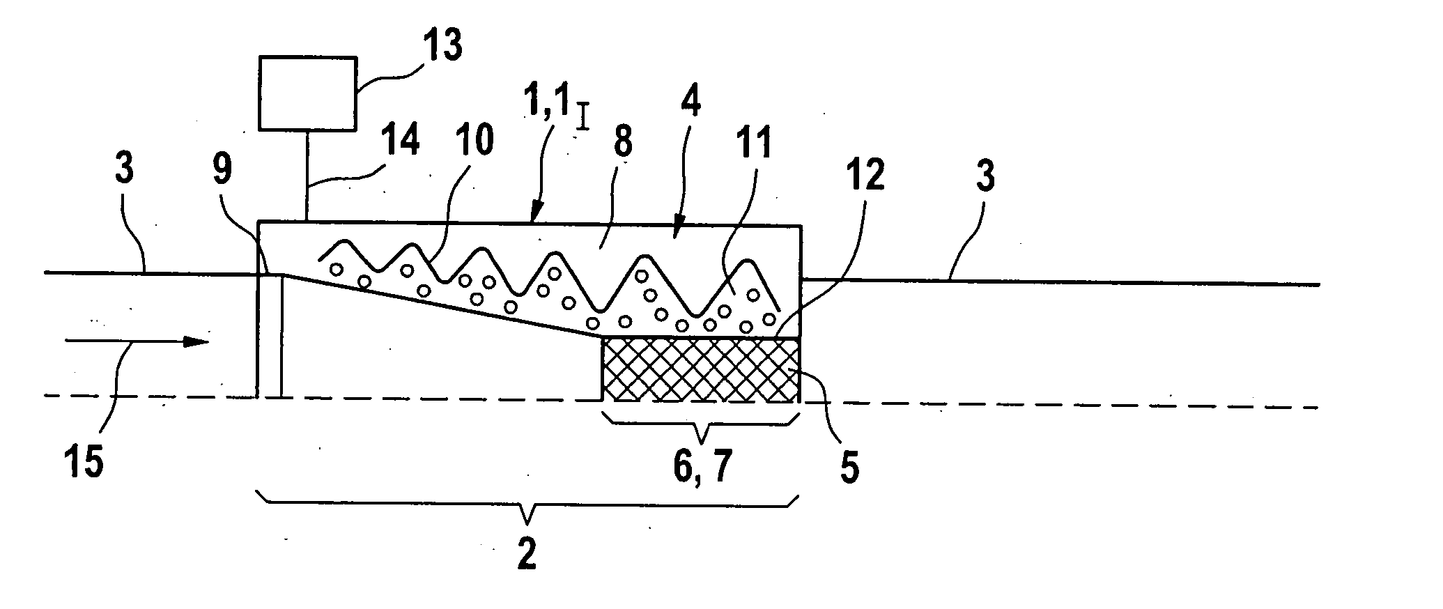
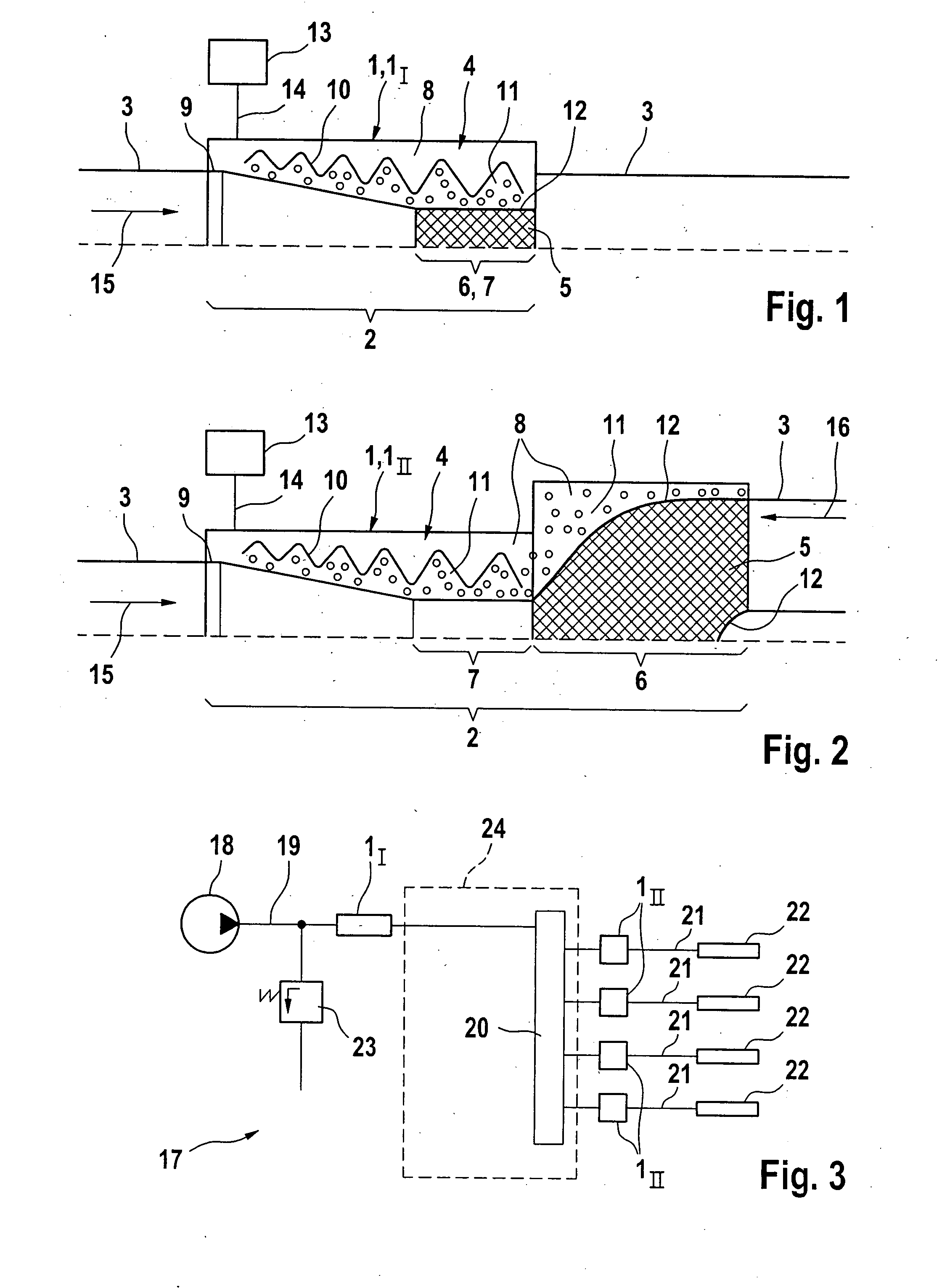
[0017] According to FIGS. 1 and 2, a control device 1 according to the invention has a line segment 2 through which a fluid can flow, which is indicated by a curly brace in the figures. When installed, the control device 1 is integrated into a hydraulic line 3, i.e. the line segment 2 constitutes a segment of the hydraulic line 3 so that the fluid transported in the hydraulic line 3 also flows through the line segment 2.

[0018] The control device 1 is also equipped with a generator apparatus 4, which makes it possible to produce a homogeneous two-phase mixture in the fluid in the line segment 2. The two-phase mixture formed in the generator apparatus 4 is symbolized in the figures by a crosshatching and is labeled with the reference numeral 5. In this way, during operation, the generator apparatus 4 forms a two-phase zone 6 inside the line segment 2, in which the two-phase mixture 5 is present and which is indicated by a curly brace and labeled with the reference numeral 6 in the fi...


PUM


Abstract

The invention relates to a device (1) for controlling the flow speed of a fluid flow in a hydraulic line (3) and has a line segment (2) that permits the fluid to flow through as well as an apparatus (4) for generating a homogenous two-phase mixture (5) in the fluid in the line segment (2).

Description

PRIOR ART [0001] The invention relates to a device and method for controlling the flow speed of a fluid flow in a hydraulic line. [0002] In a multitude of applications, it is necessary to control the speed of a fluid flow inside a hydraulic line, for example in order to set a desired flow speed and / or to eliminate or at least smooth undesirable pressure pulsations and / or to reflect pressure pulsations at least in one flow direction. Hydraulic systems in which the flow speed must be controlled in this manner are present, among other things, in motor vehicles, for example in fuel injection systems, a power steering system, and a brake system. In these highly dynamic systems, the elimination or smoothing of pressure pulsations is of particular importance. [0003] Conventional control devices such as control valves function by means of changing the effective internal geometry in terms of flow mechanics. In other words, a control valve of this kind contains a valve element that can be mov...

Claims


Application Information

Patent Timeline
Patent Type & Authority Applications(United States)
IPC IPC(8): G05D7/00
CPCG05D7/0186F02M27/08Y10T137/0329Y10T137/1026G05D7/00
Inventor IBEN, UWEHABR, KLAUS
Owner ROBERT BOSCH GMBH
Why Eureka
Try Eureka