
Digitally printed products and process

a digital printing and product technology, applied in the field of digital printing products and processes, can solve the problems of slowing down the color matching process, achieve the effects of high quality, speed up the color matching processing, and produce multiple color images

Inactive Publication Date: 2007-12-20
CCL LABEL INC
View PDF9 Cites 58 Cited by
  • Summary
  • Abstract
  • Description
  • Claims
  • Application Information

AI Technical Summary

Benefits of technology

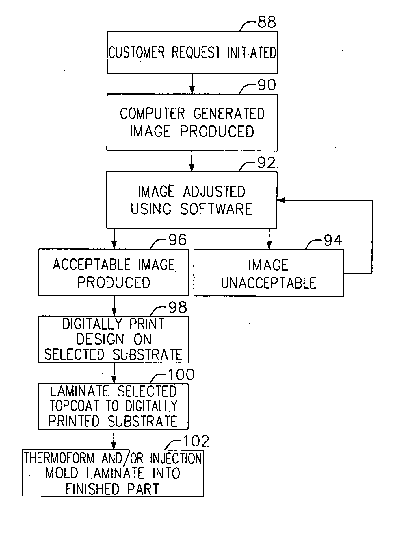
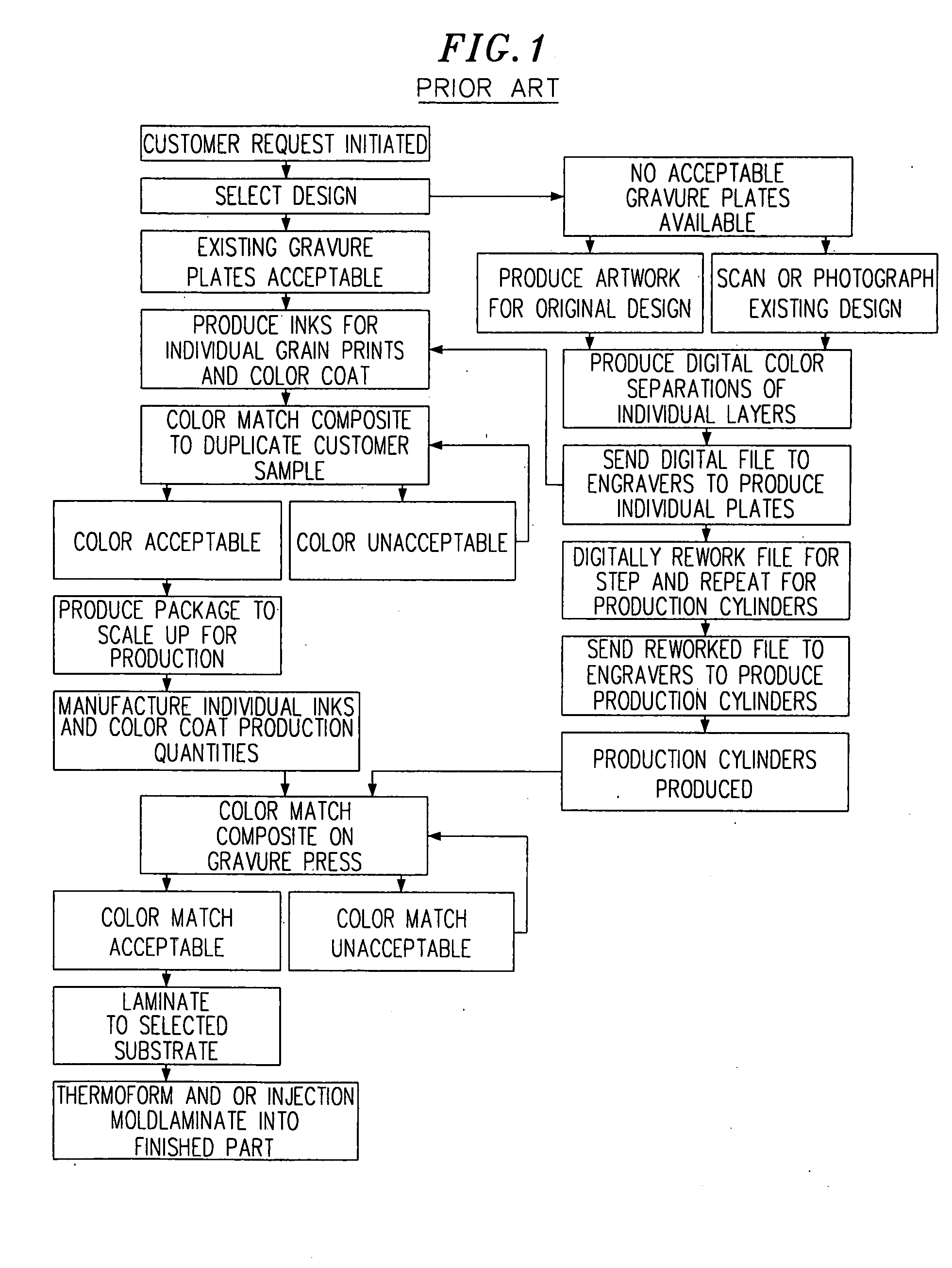
[0008] Compared with gravure printing, the digital printing process of this invention speeds the color-matching processing and the process of producing multiple color images. The invention also provides high quality digitally printed images on three-dimensionally shaped parts in which the applied ink jet images have good print quality, abrasion resistance and adhesion to the substrate. The invention also provides digitally printed laminates having a protective outer layer having exterior grade long-term weatherability, durability, and optical properties such as high gloss. Printing directly on the baseweb provides substantial cost savings. Another advantage is that one can see what the product looks like immediately after it is printed. With gravure printing, on the other hand, a sample is taken off-line and laminated to a baseweb piece, which slows the color matching process.

Problems solved by technology

With gravure printing, on the other hand, a sample is taken off-line and laminated to a baseweb piece, which slows the color matching process.

Method used


Image

  • Digitally printed products and process
  • Digitally printed products and process
  • Digitally printed products and process

Examples


example 1

[0052] This example (and Examples 2 to 4) describe digital printing on a baseweb comprising a thin polymeric film supported by a temporary carrier and subsequently laminating the baseweb to an ABS backing sheet. A roll of 1.0 mil transparent PVC film, supported by a 1.0 mil high-gloss PET temporary carrier, was placed in an ink jet printer. Images were printed directly on the surface of the film, in the absence of an ink receptive layer on the baseweb. The film was heated to 120 deg. F. immediately before contact with the print head. The laminates and films of this invention are pre-heated prior to printing for improved ink adhesion. As presently understood, 120° F. is the minimum temperature needed for good adhesion. Several images of different colors were printed side-by-side on the PVC film. These images had previously been adjusted using software that changes such print quality factors as hue, contrast, lightness / darkness, saturation, resolution, and image size.

[0053] The ink j...

example 2

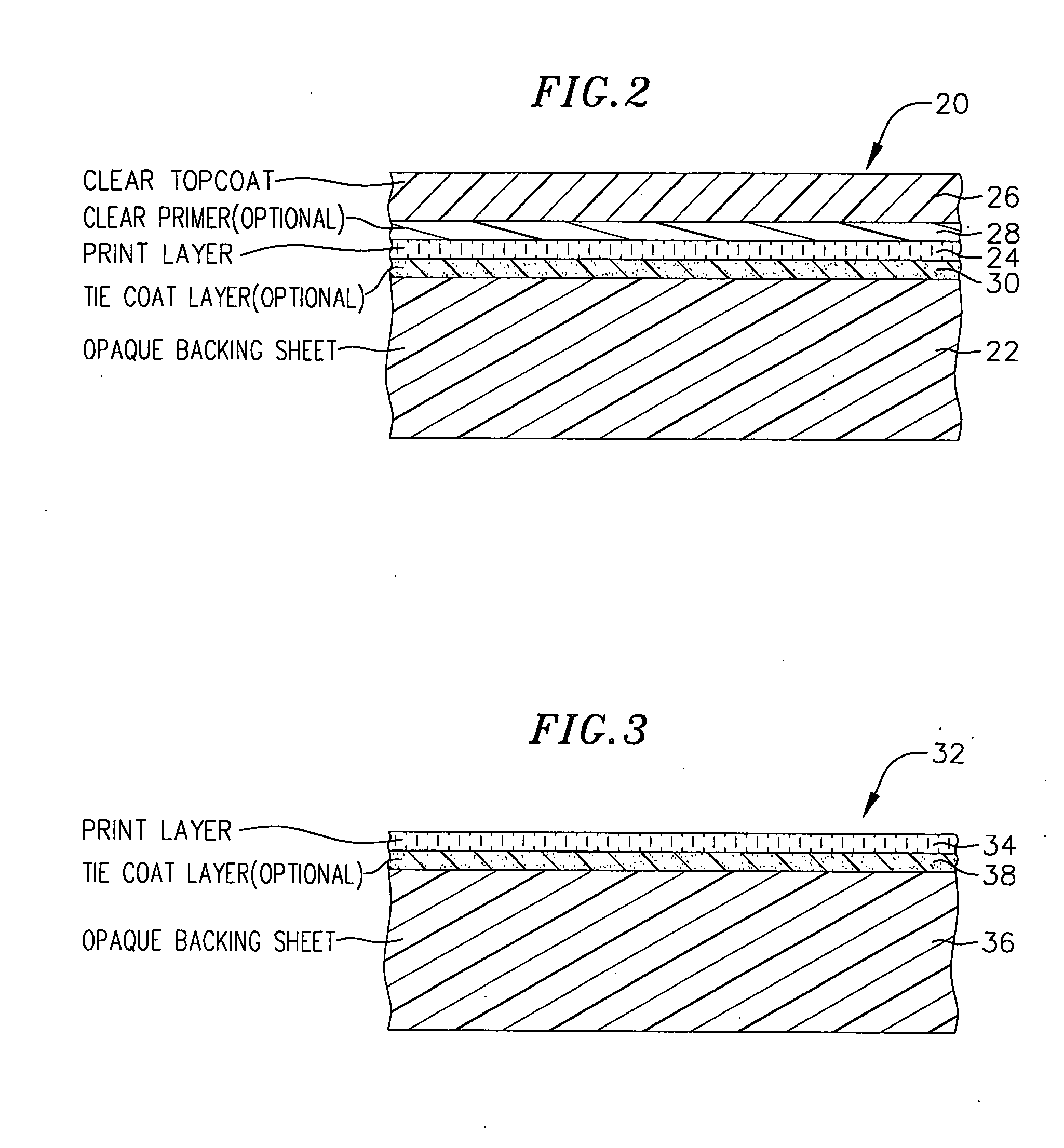
[0062] A roll of 0.7 mil transparent urethane film, supported by a 1.0 mil high-gloss PET temporary carrier, was placed in an ink jet printer. The same printer, printing inks, printing rate, resolution, and images were used as in Example 1. The urethane film did not have an ink receptive layer. The urethane film was heated to 160 deg. F. immediately before contact with the print head. The higher film pre-heat temperature (as compared to Example 1) was found to give a better print appearance for the urethane.

[0063] The ink jet images were printed directly onto the film surface, and the film was again heated in-line with an infrared heater, to a film temperature of 120 deg. F., for solvent drying the printing inks.

[0064] After the film was removed from the printer, it was tested for retained solvent. The retained solvent was 8.8%, which is comparable to a gravure printed sample of urethane.

[0065] The same laminating, thermoforming, and injection molding steps were used as in Exampl...

example 3

[0067] A roll of 1.8 mil transparent PVDF / acrylic film, supported by a 2.0 mil high-gloss PET temporary carrier, was placed in an ink jet printer. The same printer, printing inks, printing rate, film pre-heat temperature, infrared heating, resolution, and images were used as in Example 2. The film did not have an ink receptive layer.

[0068] After the film was removed from the printer, it was tested for retained solvent. The retained solvent was 2.9%, which is comparable to a gravure printed sample of PVDF / acrylic film.

[0069] The same laminating, thermoforming, and injection molding steps were used, as in Examples 1 and 2.

[0070] The resulting injection molded part was tested in the Xenon Weatherometer, using the SAE J1885 test spec. After 500 and 1240 kilojoules exposure, the sample had retained its original gloss and DOI.

[0071] In addition, thermoformed (but not injection molded) samples were subjected to the following tests:

[0072] 2000 hours QUV (ASTM G53 spec.)

[0073] 2000 hou...


PUM

PropertyMeasurementUnit
Temperatureaaaaaaaaaa
Lengthaaaaaaaaaa
Lengthaaaaaaaaaa

Abstract

A process for manufacturing three-dimensionally shaped polymeric sheets and laminates with color-matched digitally printed full color ink jet images. A flexible thermoformable polymeric baseweb is placed in an ink jet printer and a solvent-based (non-aqueous) digital printing ink is applied directly to the baseweb, in the absence of an ink receptive layer on the baseweb, to form a decorative pattern in multiple colors in a single pass through the printer. The finished product can be thermoformed or injection molded to a three-dimensional shape. A protective topcoat can be laminated to the digitally printed sheet prior to the thermoforming and / or injection molding step. A process for making color-matched products comprises producing a software-driven image of a pattern on a screen representing a standard color print pattern; evaluating and adjusting the standard displayed on the screen using software-driven image related adjustments for hue, contrast, lightness / darkness, etc.; producing a test print by applying a decorative pattern to the baseweb by a digital ink jet printer and making an optional software-driven image-related adjustment in the standard to color match the standard to the test print image; and when the adjusted standard image displayed on the screen is acceptable, passing an image-related output to the digital ink jet printer for printing a decorative print color-matched to the accepted onscreen standard.

Description

FIELD OF THE INVENTION [0001] This invention relates to ink jet printing of color images on polymeric sheets and laminates, and more particularly to the manufacture of three-dimensionally shaped polymeric sheets and laminates with color-matched digitally printed full color ink jet images. BACKGROUND OF THE INVENTION [0002] Three-dimensionally shaped polymeric sheets and laminates are commonly printed with full color decorative print patterns. The printed sheets or laminates can be bonded to an injection molded substrate to make the finished part. These products can include interior automotive parts such as dashboard parts and gauges with decorative finishes, including decorative wood grain, and other products such as cell phones, personal electronic equipment (MP3 and CD players), EMI / RFI shielding, signs, and outdoor siding panels, for example. [0003] These products are commonly made by a gravure printing process in which color separations in individual layers are initially sent to...

Claims


Application Information

Patent Timeline
IPC IPC(8): B32B38/14B41J2/01B05D5/06B05D7/00B29C45/14B32B27/08B32B33/00B41C3/08B41M3/00B41M5/00B41M5/50B41M5/52B41M7/00
CPCB29C45/14688B29C2045/14737B32B27/08B41M3/00B41M5/0047B41M5/0064B41M5/508B41M7/0027Y10T156/1079B41M5/00B32B38/14B32B2307/738B32B27/40B32B2307/4023B32B2307/406B32B7/12B32B2333/04B32B2307/71B32B2375/00B32B2250/24B32B2327/00B32B27/308B32B27/304
Inventor JOHNSON, JOHNROEDEL, JERRY
Owner CCL LABEL INC
Learn More