
Guidewire With Lubricious Proximal Portion

a technology of proximal portion and guidewire, which is applied in the direction of guide wire, catheter, diagnostic recording/measuring, etc., to achieve the effect of reducing resistance and/or locking

Inactive Publication Date: 2007-12-20
ABBOTT CARDIOVASCULAR
View PDF21 Cites 18 Cited by
  • Summary
  • Abstract
  • Description
  • Claims
  • Application Information

AI Technical Summary

Benefits of technology

[0009]Briefly, and in general terms, the present invention provides a new and improved guidewire having a lubricious proximal portion. The lubricious proximal portion reduces resistance and / or lock up caused by interaction between the proximal portion and clotted blood, dried contrast, or combinations thereof that normally adhere to the proximal section of the guide wire.
[0011]In one embodiment of the invention, the proximal portion is coated with a base coat of a lubricious coating such as TEFLON®, although a variety of other base coats can be used. Then, at least one top coat of a different lubricious coating such as, for example, a silicone-based coating, is applied over the base coat. This combination of base coat and top coat imparts a lubricity that improves the ability of the guidewire to overcome resistance and prevent lock up during use.
[0013]Another approach is to provide a guidewire in which the proximal portion is coated with a first base coat of lubricious coating. A top coat of a second, hydrophobic, lubricious coating is applied on the base coat. The distal portion, on the other hand, is coated with a hydrophilic coating. This combination of a hydrophobic, particularly lubricious coating on the proximal portion and a hydrophilic coating on the distal portion is particularly well-suited to the operation of the guidewire. The hydrophilic coating is advantageous on the distal portion of the guidewire that comes into contact with the arterial walls, whereas the hydrophobic, lubricious coating on the proximal portion prevents undesired resistance from blood clots and the like as the guidewire moves through the catheter.

Problems solved by technology

A problem can arise in practice, as the guidewire moves through the catheter and encounters clumps of clotted blood, dried contrast, or combinations thereof that adhere to the proximal section of the guide wire.
The guidewire tends to meet movement resistance within the catheter, and may even lock up.

Method used


Image

  • Guidewire With Lubricious Proximal Portion
  • Guidewire With Lubricious Proximal Portion
  • Guidewire With Lubricious Proximal Portion

Examples


Embodiment Construction

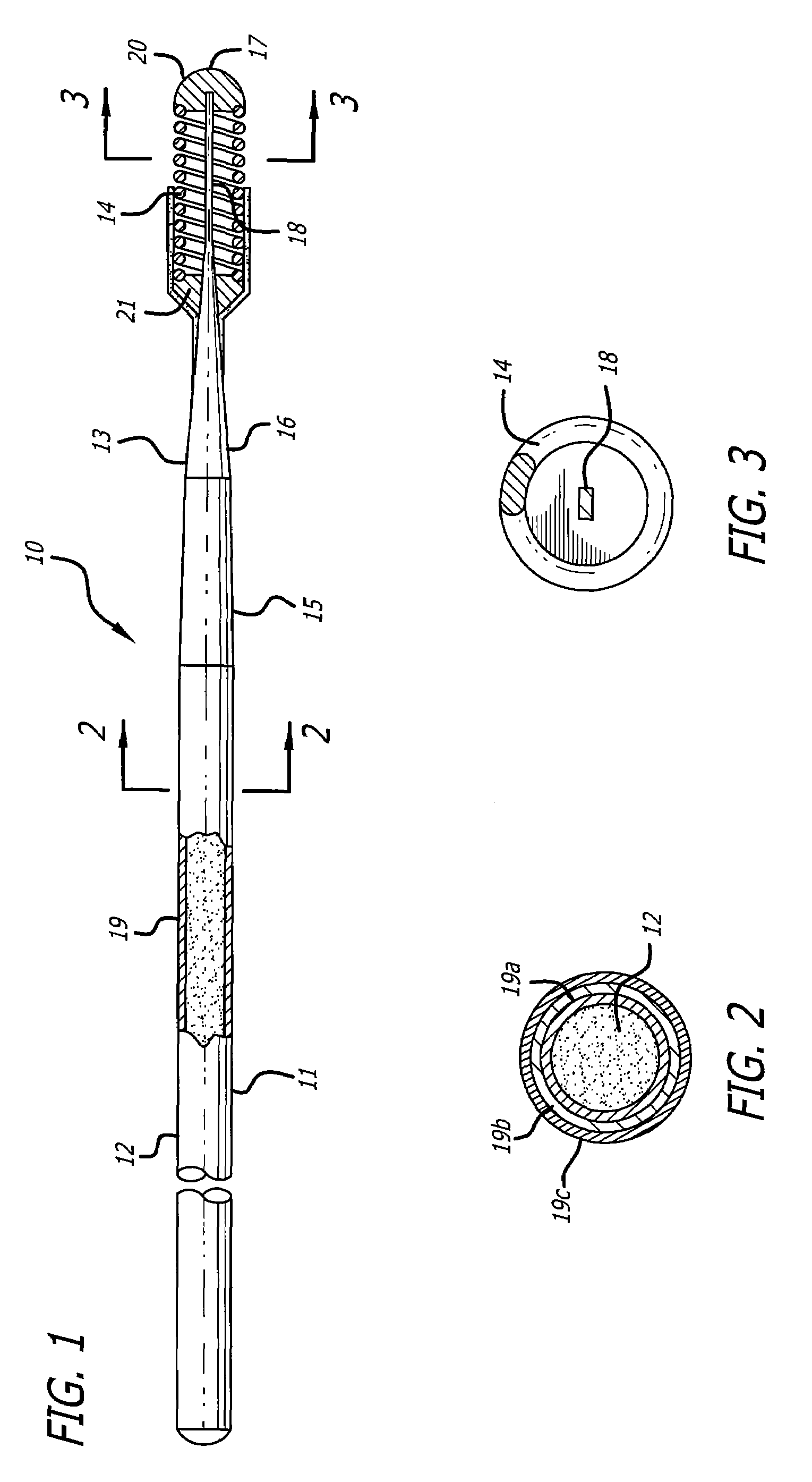
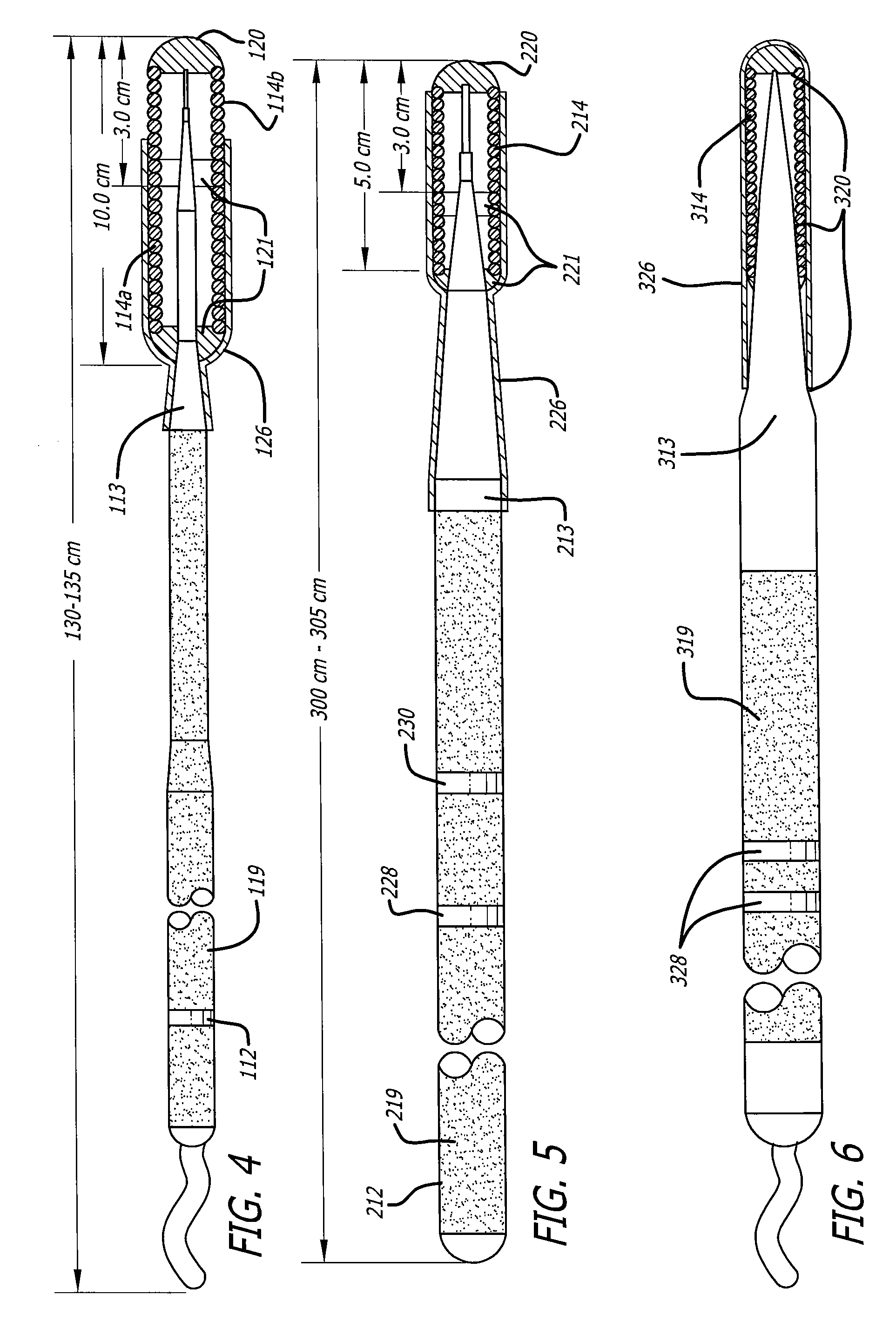
[0023]FIGS. 1-3 depict a guidewire 10 which has a core member 11 with a proximal core section 12, a distal core section 13 and a helical coil 14. The distal core section 12 has a first tapered segment 15 and a second tapered core segment 16 which is distally contiguous to the first tapered core segment. The second tapered segment 16 tapers at a greater degree than the first tapered segment and this additional taper provides a much smoother transition when the distal portion of the guidewire 10 is advanced through a tortuous passageway. The degree of taper of the first tapered core segment 15, i.e. the angle between the longitudinal axis 17 and a line tangent to the first tapered core segment 15 is about 2° to about 10°, whereas the taper of the second tapered core segment 16, i.e. the angle between the longitudinal axis and the second tapered core segment is larger than the first angle and is about 5° to about 10° such as is shown in the enlarged view of the guidewire 10 in FIG. 4. ...


PUM

PropertyMeasurementUnit
Hydrophilicityaaaaaaaaaa
Hydrophobicityaaaaaaaaaa

Abstract

A guidewire has a proximal portion and a distal portion. The distal portion may be coated, as with a hydrophilic or other coating, or may be uncoated. The proximal portion, however, is coated with a specially lubricious coating that serves to reduce resistance and to prevent lock up as the guidewire moves through a guiding catheter. The proximal portion may, for example, be coated with a base layer, such as TEFLON® (polytetrafluoroethylene), and one or more top layers, such as a silicone-based layer. In one approach, two silicone-based top layers are applied. Alternatively, a top layer of spray PTFE, paraffins, olefins, and / or fats may be applied. As an alternative, the base layer may be optional, such that the top layer or layers is coated onto bare metal, or a base other than TEFLON® may be used.

Description

BACKGROUND OF THE INVENTION[0001]This invention relates to the field of guidewires for advancing intraluminal devices such as stent delivery catheters, balloon dilatation catheters, atherectomy catheters and the like within body lumens.[0002]In a typical coronary procedure a guiding catheter having a preformed distal tip is percutaneously introduced into a patient's peripheral artery, e.g. femoral or brachial artery, by means of a conventional Seldinger technique and advanced therein until the distal tip of the guiding catheter is seated in the ostium of a desired coronary artery. There are two basic techniques for advancing a guidewire into the desired location within the patient's coronary anatomy, the first is a preload technique which is used primarily for over-the-wire (OTW) devices and the bare wire technique which is used primarily for rail type systems.[0003]With the preload technique, a guidewire is positioned within an inner lumen of an OTW device such as a dilatation cath...

Claims


Application Information

Patent Timeline
IPC IPC(8): A61M25/09
CPCA61L31/10A61L31/14A61L2420/08A61M25/09A61M2025/09091C08L27/18C08L83/04
Inventor LEE, JEONGBALDWIN, AARONWHITE, ROSEMINDANOLAN, KRISTEN M.BIAGTAN, EMMANUEL C.
Owner ABBOTT CARDIOVASCULAR
Learn More