Three-Dimensional Decoration Piece Made Of Synthetic Resin And Method Of Manufacturing The Same

a technology of synthetic resin and decoration pieces, which is applied in the field of three-dimensional decoration pieces made of synthetic resin and the same manufacturing method, can solve the problems of difficult cutting operation, inability to manufacture three-dimensional decoration pieces, and inability to use sticking materials such as sticky tapes for the lining layer, so as to achieve easy removal and increase bonding strength

Active Publication Date: 2007-12-27
NOBUO KURODA +2
View PDF4 Cites 17 Cited by
  • Summary
  • Abstract
  • Description
  • Claims
  • Application Information

AI Technical Summary

Benefits of technology

[0043] In the third and fourth aspects of the invention, the three-dimensional molded body of the upper and intermediate layers is welded to the base member on a cathode having a flat surface, the base member is not stretched by indented and protruding molds. Therefore, this invention provides an advantage that the base member is not required to have an stretchable characteristic. Additionally, the welding process is conducted on a flat cathode, so that neither the three-dimensional molded body of the upper and intermediate layers nor the base member is stretched. Then, the three-dimensional molded body of the upper and intermediate layers and the base member can be welded over the entire surf...

Problems solved by technology

However, the outer part is pulled by the fusion cutter at the time of cutting, so as to make the cutting operation difficult.
Therefore, if a bonding or sticking layer is to be formed on the rear surface of the three-dimensional piece as a lining layer during the manufacturing process, it is not possible to use a sticking material such as a sticky tape for the lining lay...

Method used


Image

  • Three-Dimensional Decoration Piece Made Of Synthetic Resin And Method Of Manufacturing The Same
  • Three-Dimensional Decoration Piece Made Of Synthetic Resin And Method Of Manufacturing The Same
  • Three-Dimensional Decoration Piece Made Of Synthetic Resin And Method Of Manufacturing The Same

Examples


fourth embodiment

[0060] As will be described hereinafter, a three-dimensional decoration piece is manufactured by a method according to the present invention, using an upper layer material, an intermediate layer material and a lower layer material, except the The upper layer material and the intermediate layer material may be laid in advance to form an integral unit.

[0061] The upper layer material may be thermoplastic synthetic resin film as it is to make a surface of the manufactured three-dimensional decoration piece esthetically appealing. Examples of materials that can be used as the upper layer material include polyvinyl chloride film, polyurethane film, polyester film and polyolefin film etc.

[0062] Metal may be deposited on the thermoplastic synthetic resin film by evaporation to make the three-dimensional decoration piece appear as if it were made of metal. Examples of such materials include metal deposited polyvinyl chloride film, metal deposited polyurethane film, metal deposited polyeste...

first embodiment

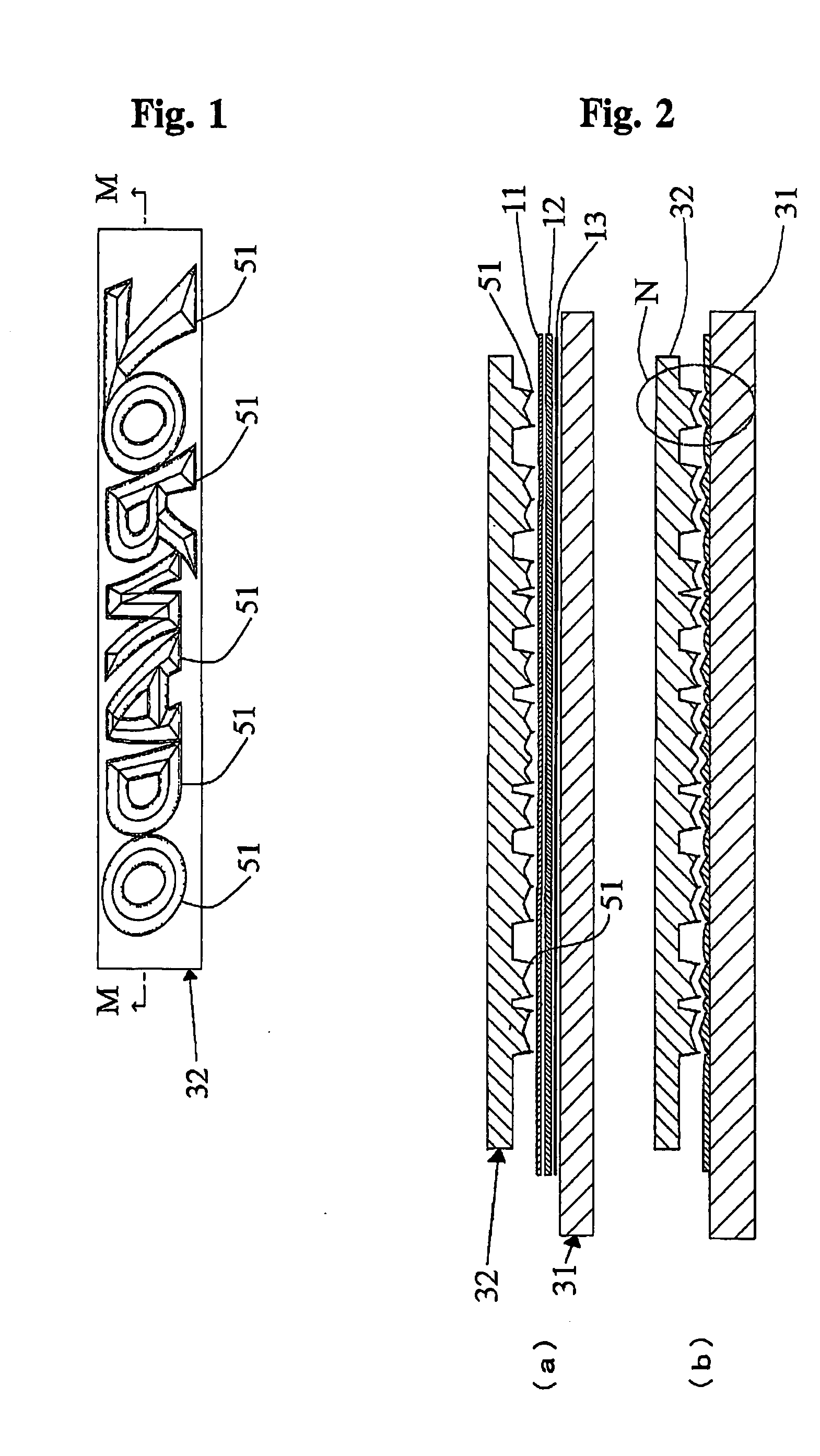
[0072]FIGS. 1-4 illustrate the present invention.

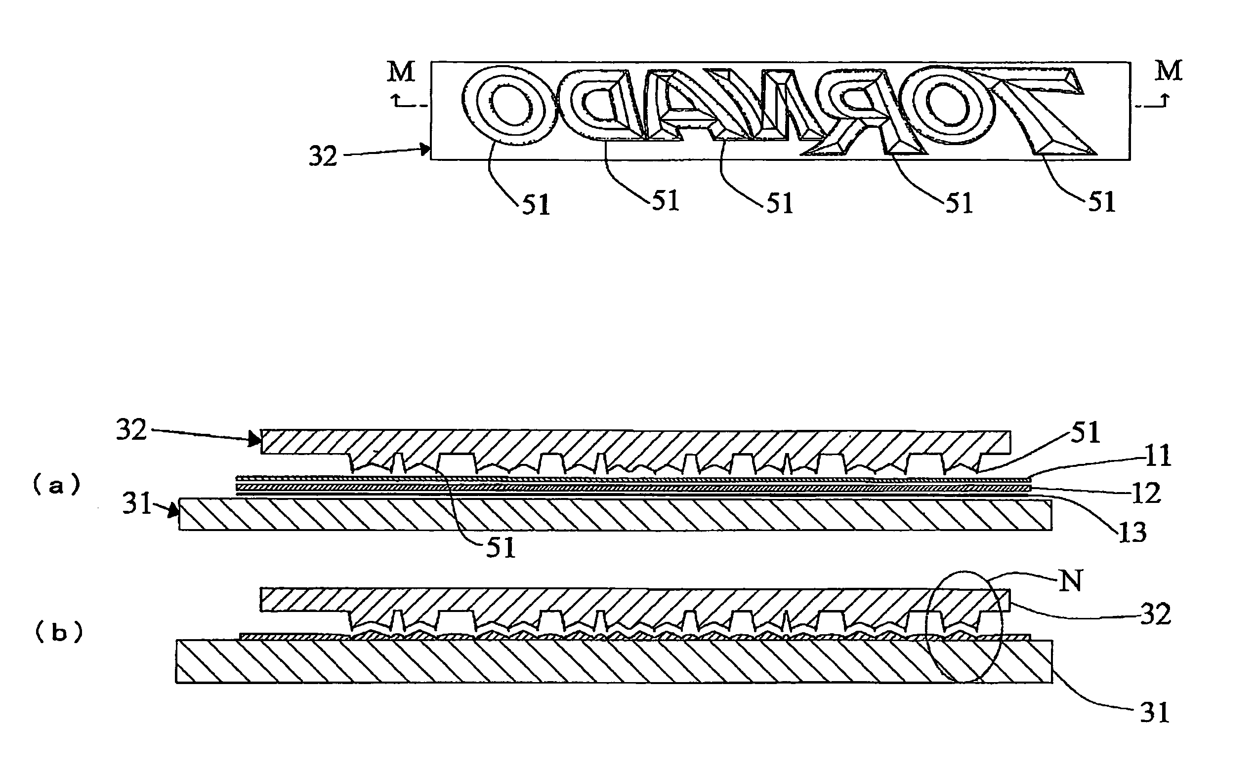
[0073]FIG. 1 is a schematic bottom view of the indented mold 32 that is employed in the first embodiment of the invention. FIG. 2A is a schematic sectional view of the indented mold 32 taken along line M-M in FIG. 1, with the upper layer material 11, the intermediate layer material 12, the lower layer material 13 and the table 31. It shows a state before the high frequency dielectric heating step. FIG. 2B is a schematic sectional view similar to FIG. 2A, but shows a state after the high frequency dielectric heating step and after pulling up the indented mold 32.

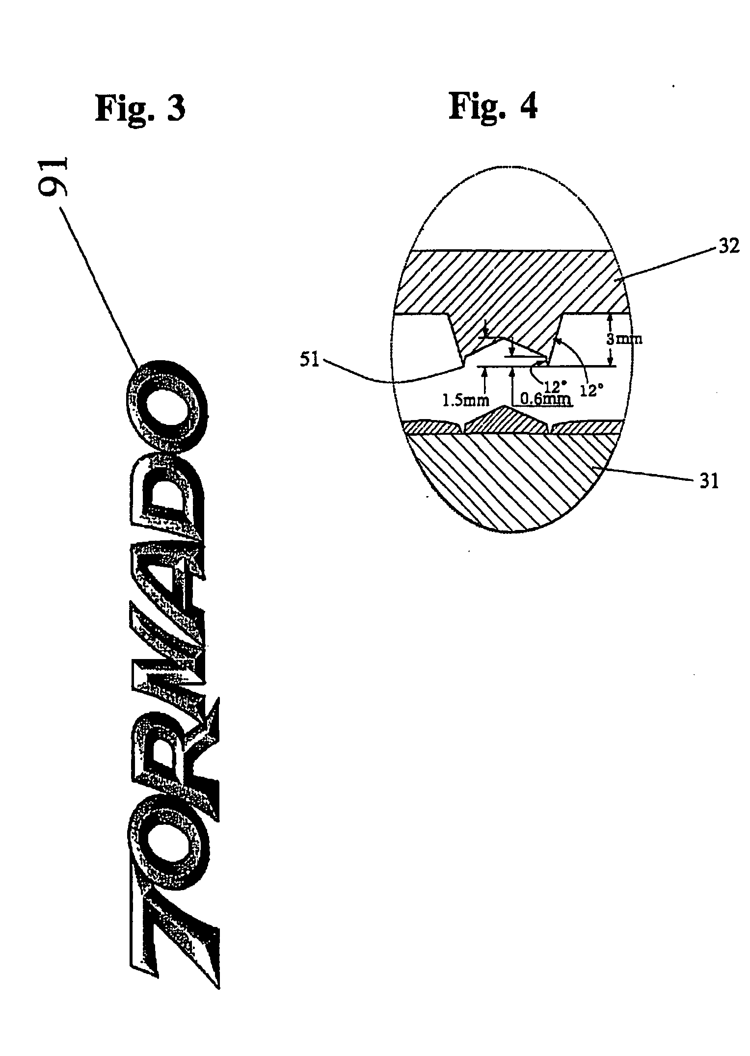
[0074]FIG. 3 is a schematic plan view of a three-dimensional decoration piece 91 manufactured by the first embodiment of the invention.

[0075]FIG. 4 is an enlarged schematic view of the area N surrounded by an ellipse in FIG. 2.

[0076] A high frequency dielectric heater to be used for the first embodiment includes a table 31, which is a cathode, and an indented mold 32 that op...

second embodiment

[0083] Now, the present invention will be described below.

[0084] In the second embodiment, an indented mold is provided with a second fusion cutter which is arranged outside the fusion cutter of the above described first embodiment, to manufacture a three-dimensional decoration piece. The three-dimensional decoration piece manufacturing method of the second embodiment comprises:

(1) laying sequentially a lower layer material, an intermediate layer material and an upper layer material on a cathode (table or a flat mold) having a flat surface; and

(2) pressing the material layers from above by an indented mold (132) operating as anode, and melting and molding the materials by high frequency dielectric heating.

[0085] The indented mold (132) is equipped not only with a first fusion cutter (151) but also a second cutter (a fusion cutter or a pressing blade) 152. The first cutter (151) corresponds to a contouring part of the three-dimensional decoration piece, and is adapted to cut a p...


PUM

PropertyMeasurementUnit
Lengthaaaaaaaaaa

Abstract

There are provided (1) a method of manufacturing a three-dimensional decoration piece having a flat rear surface, (2) a method of manufacturing the decoration piece by easily cutting the same by means of a fusion cutter, (3) a method of manufacturing the decoration piece having a bonding or sticking feature on the rear surface and (4) a method of manufacturing a three-dimensional decoration piece without limiting the characteristics of the base member thereof. The three-dimensional decoration piece is manufactured by using an indented mold and high frequency dielectric heating. An indented mold having a second fusion cutter and arranged along an outer periphery of the fusion cutter is used. Firstly, a three-dimensional molded body of upper and intermediate layers having a recessed section on a lower surface thereof is molded by means of an indented mold and a protruding mold, and subsequently a lower layer material is molten by high frequency dielectric heating and made to flow into the recessed section. Firstly, a three-dimensional molded body of upper and intermediate layers is molded, and subsequently the three-dimensional molded body is welded to a base member by means of high frequency dielectric heating.

Description

BACKGROUND OF THE INVENTION [0001] This invention relates to an improvement to a method of manufacturing a decoration piece of synthetic resin that is adapted to be mainly fitted to an automobile, a bicycle, a motor boat, an OA apparatus, a home use electric appliance, a sporting good, a writing article, a bag, a wear or the like. [0002] JP-B-05-018698, JP-B-07-102620 and JP-B-3235943 disclose methods of manufacturing a three-dimensional decoration piece of synthetic resin such as an emblem, using a metal mold and high frequency dielectric heating. [0003] However, the inventions disclosed in the above JP-B-05-018698 and JP-B-07-102620 employ both a protruding mold and an indented mold. A three-dimensional decoration piece is manufactured between the protruding mold and the indented mold. Thus, the manufactured three-dimensional decoration piece is not flat at the rear surface, but has a recess (hollow) at the rear side. Then, the area of the piece to be bonded or to be made to adher...

Claims


Application Information

Patent Timeline
IPC IPC(8): B27N3/20
CPCB29C35/12Y10T428/24479B29C43/40B29C59/026B29C65/04B29C65/7441B29C66/4724B29C2043/023B29K2105/256B29L2031/722B29L2031/723B44C1/24B44C3/046B29C43/021B29C65/00B29C66/8322B29C66/1122B29C66/45B29C66/81427B29C66/71B32B38/06B29C66/81431B29C65/7841B29K2023/00B29K2023/083B29K2027/06B29K2067/00B29K2075/00B29K2077/00B27N3/20
Inventor KUWAHAHA, EIJI
Owner NOBUO KURODA
Why Eureka
Try Eureka