

Aperture-coupled antenna
- Summary
- Abstract
- Description
- Claims
- Application Information
AI Technical Summary
Benefits of technology
Problems solved by technology
Method used
Image

Examples
first embodiment
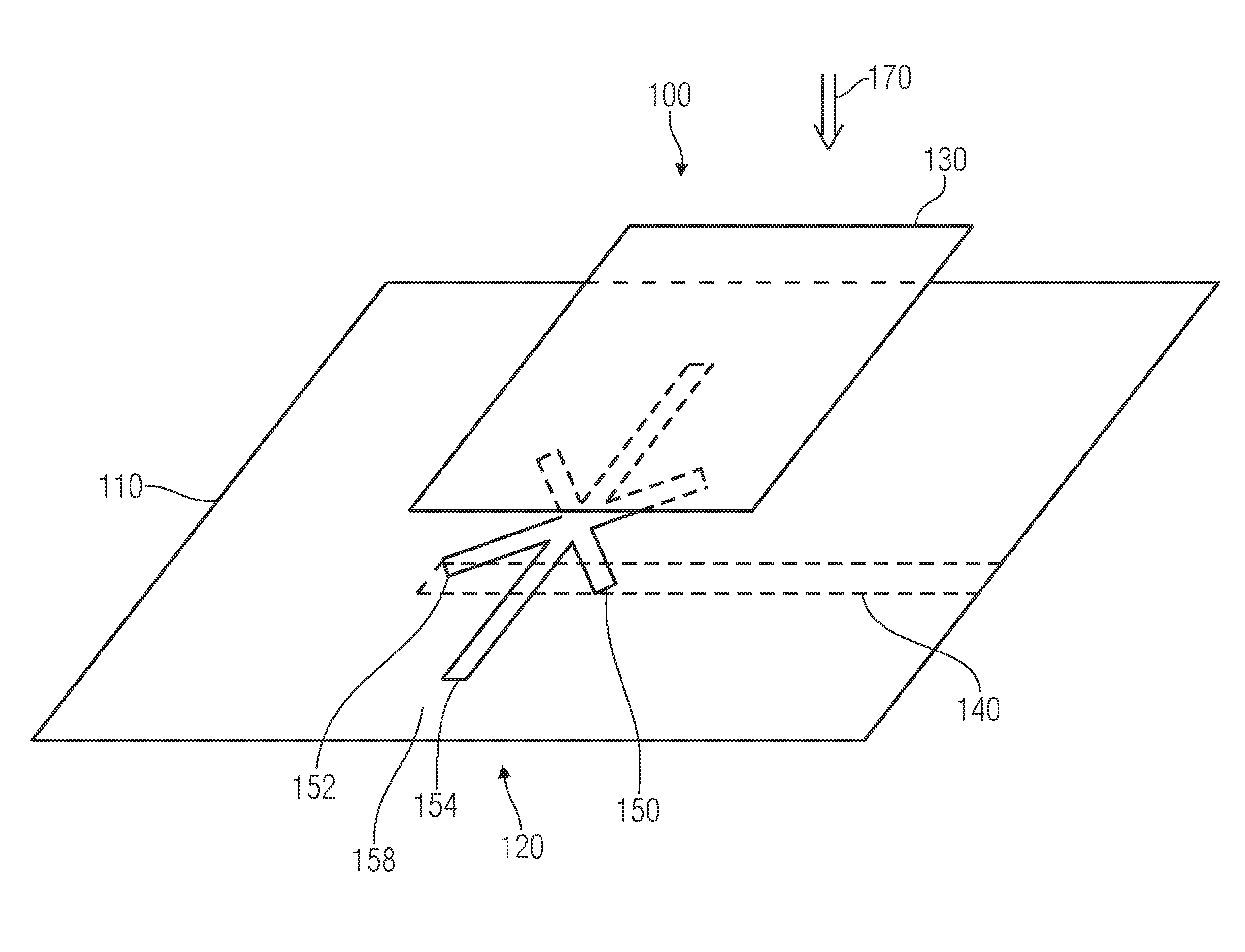
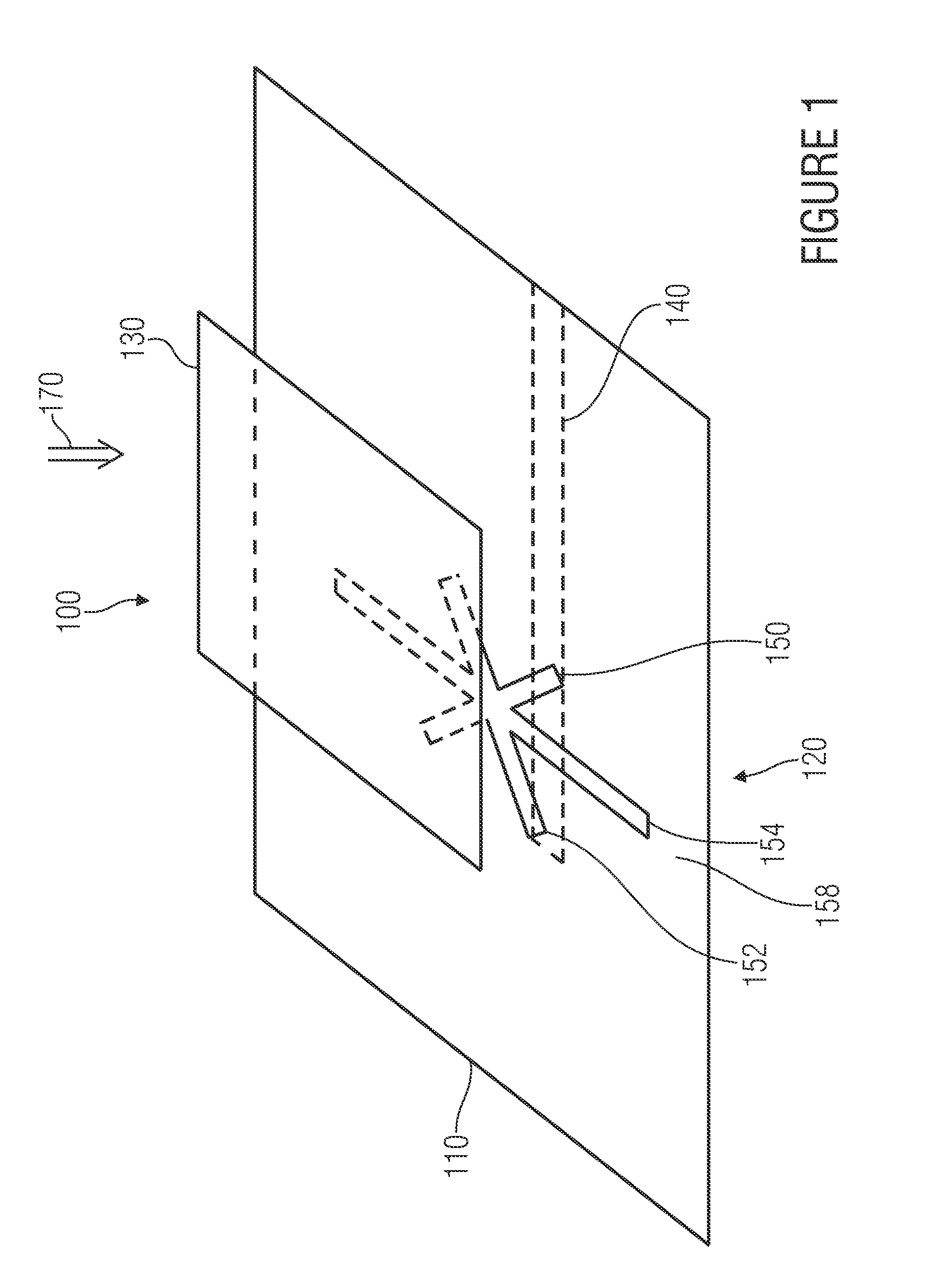
[0049]FIG. 1 shows a tilted image of an inventive antenna structure according to the present invention. The antenna structure in its entirety is referred to by 100. The antenna structure 100 includes a ground area 110 comprising an aperture 120. In addition, the antenna structure includes a radiation electrode 130 arranged above the ground area 110. A feeding line 140 which is shown here as a conducting strip is arranged below the ground area 110. The aperture 120 includes a first slot 150, a second slot 152 and a third slot 154. The first, second and third slots 150, 152, 154 each have a rectangular shape and represent an opening of the ground area 110. The first slot 150 and the second slot 152 are arranged so as to form a cross. The lengths of the first slot 150 and the second slot 152 in the embodiment shown are equal. The third slot 154 is longer than the first slot 150 and the second slot 152 and intersects the first and second slots 150, 152 in the region in which the first a...
second embodiment
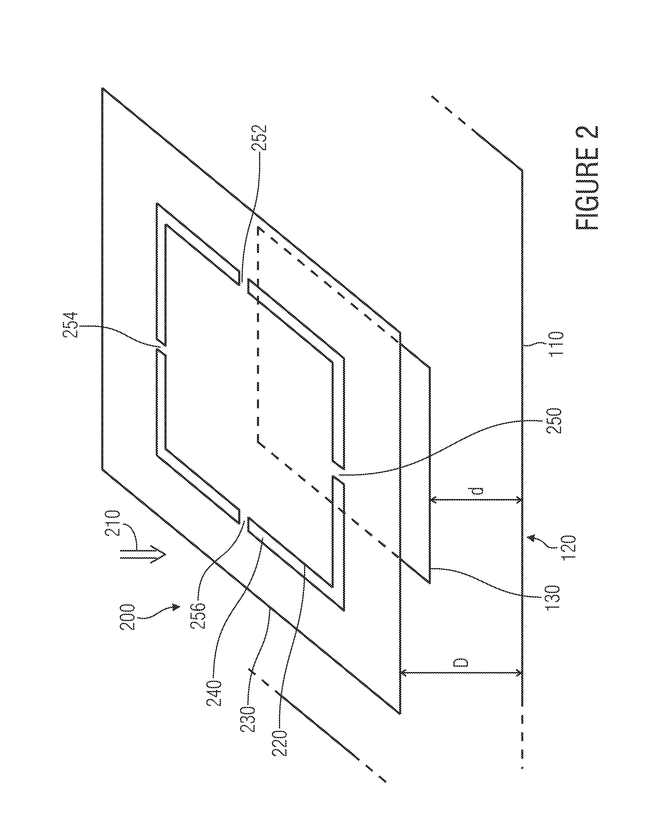
[0060]FIG. 2 shows a tilted image of an inventive radiator geometry according to the present invention. The radiator geometry in its entirety is referred to by 200. It is pointed out that in FIGS. 1 and 2 and also in the remaining figures, same reference numerals refer to same means. A ground area 110 comprising an aperture 120 is shown here. Specific details of the aperture are not shown here for reasons of clarity, however the aperture corresponds to the one described and shown in FIG. 1. Additionally, the inventive radiator geometry 200 includes a first radiation electrode 130. The aperture 120 represents an opening in the ground area 110 which in a top view along a direction characterized by the arrow 210 is below the first radiation electrode 130. A second radiation electrode 220 is arranged above the first radiation electrode. It is enclosed by the third radiation electrode 230, wherein there is a gap 240 between the second radiation electrode 220 and the third radiation elect...
third embodiment
[0072]FIG. 3 shows a tilted image of an inventive antenna structure according to the present invention. The antenna structure in its entirety is referred to by 300. It basically corresponds to the antenna structure 100 shown referring to FIG. 1, so that same means and geometry characteristics here are provided with same reference numerals. Unchanged characteristics will not be described again. However, it is pointed out that in the antenna arrangement 300 a first corner 310 and a second corner 320 of the first radiation electrode 130 are cut off and / or bevelled. This geometrical alteration contributes to the fact that a circularly polarized electromagnetic wave can be radiated. In addition, the antenna arrangement 300 comprises a stub 330 applied to the strip line 140. This stub 330 serves further impedance matching of the present antenna structure. The dimensioning of such a stub for matching is known to one skilled in the art.
[0073] In addition, FIG. 3 shows an enclosing cuboid 34...
PUM
 Abstract
Description
Claims
Application Information