[0011] The present invention provides a multi-zone
contact lens for inhibiting the progression of myopia in an eye, a method of forming such a lens, and a method of inhibiting the progression of myopia in an eye by the use of such a lens. The lens basically has a central optical zone that approximates in size the normal
pupil diameter of the eye and that has a refractive power selected or adapted to give the eye clear distance vision, and a peripheral optical zone that substantially falls outside the normal
pupil diameter of the eye and that has a refractive power sufficient to focus oblique peripheral rays entering the patient's eye through the
peripheral zone onto a focal plane located on or in front of the peripheral region of the retina. While such peripheral focus provides the stimulus for reducing elongation of the eye in accordance with the teachings of Smith, two-zone lenses of this type—especially where the
peripheral zone is annular and surrounds the central zone—are much more readily and cheaply made than the lenses disclosed in the Smith patent and can potentially introduce less aberrations such as
distortion to the peripheral image.
[0014] On the other hand, it is preferred that the
maximum diameter of the central zone should not be more than 1 mm greater than the normal
pupil diameter. Where an annular peripheral optical zone is employed, the inner diameter preferably approximates the outer diameter of the central zone and the outer diameter will normally be less than 8 mm. The total diameter of the contact lens will typically lie between 13-15 mm, the additional area being formed by a skirt-like ring or carrier portion that serves to assist in locating and retaining the lens in position on the eye.
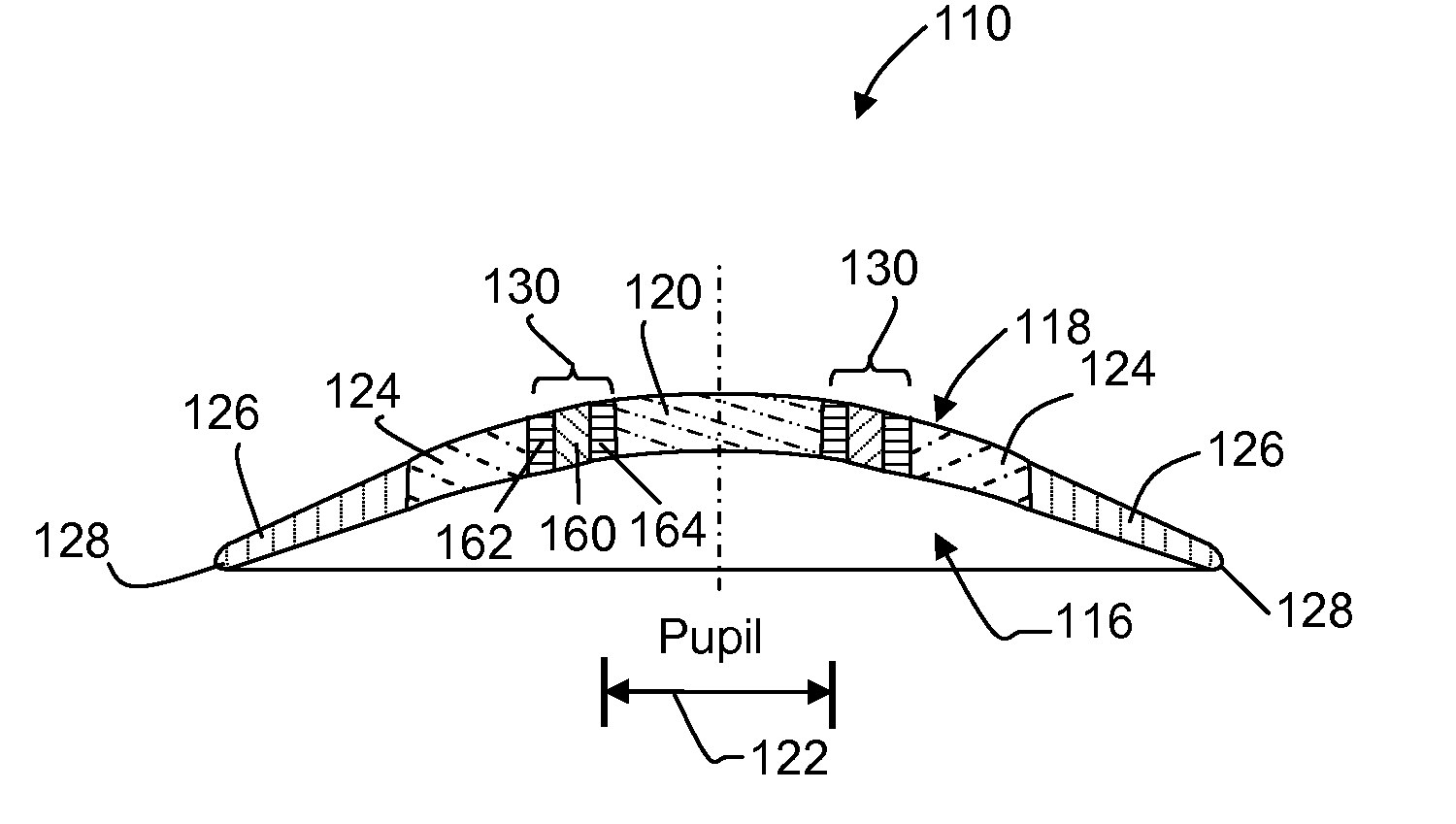
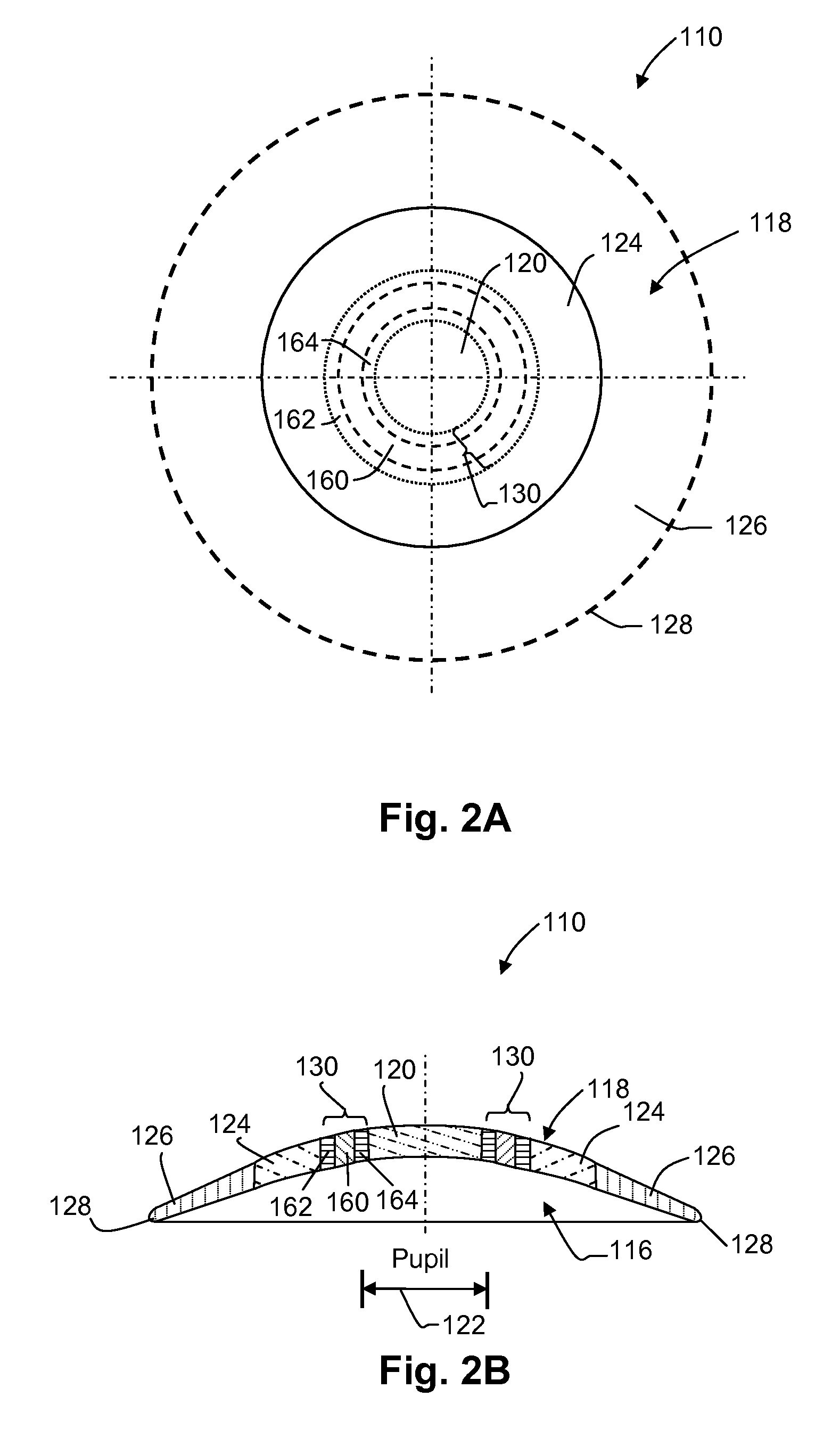
[0015] As is common with contact lenses, the rear surface is shaped to conform to the shape of the
cornea of the patient and the front surface is contoured to create—together with the shape of the rear surface—the desired optical zones with their respective refractive powers. However, with the contact lenses herein envisaged, the difference in refractive power between the central zone and the peripheral optical zone can be as great as 8 Diopters and the discontinuity in shape of the front lens surface at the junction of the central and peripheral zones can be significant. Accordingly, it may be desirable to shape the front of the lens at this junction to form a transition zone which smooths the transition between the shapes of the different zones and / or which provides progressive increase in refractive power in a
narrow band between the zones. The purpose of the transition zone, however, is to both smooth the external surface of the lens and to reduce optical artifacts and distortions that may be introduced by a sudden change in refractive
power over a
short distance. Simply blending or filleting the curves is often sufficient even though it may provide a narrow ring with indeterminate refractive properties.
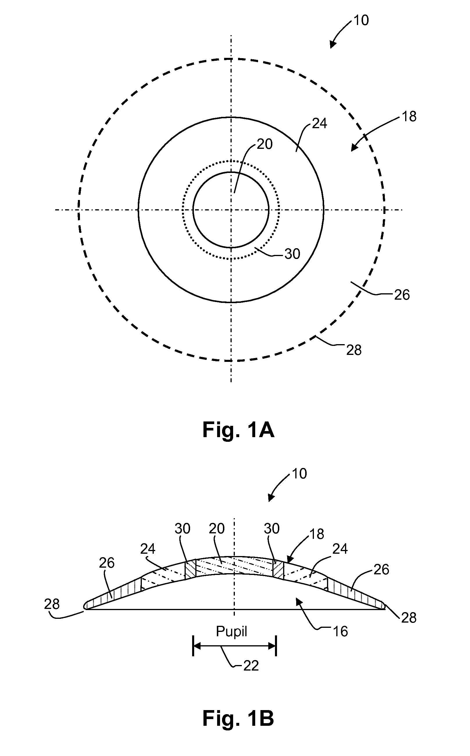
[0019] Still further, according to embodiments of the present invention, the present invention is directed to a contact lens for use in reducing the progression of myopia in an eye of a wearer comprising a transparent material having front and rear surfaces, wherein the rear surface provides a base-curve adapted to fit the eye; and wherein the front surface comprises; a central optical zone curved so that, together with the base-curve, said central optical zone produces a central optical zone refractive power adapted to provide the wearer with clear distance vision in a
central region of the retina of the eye, the central optical zone being substantially circular in shape of at least 3 mm in diameter but not more than 1 mm less than the normal diameter of the pupil of the eye; and an annular peripheral optical zone surrounding said central zone and curved so that, together with the base-curve, said
peripheral zone is adapted to produce a peripheral optical zone refractive power, when the lens is worn, that is greater than said central optical zone refractive power by an amount greater than 1 Diopter and sufficient to focus off-axis rays that enter the eye through said peripheral zone onto a focal plane that is substantially on, or anterior to, the retina in a peripheral region of the retina located around said
central region.
[0020] Still further, embodiments of the present invention are directed to a method for forming a contact lens for reducing the progression of myopia in an eye of a wearer, comprising forming on a transparent material a rear surface comprising a base-curve that is adapted to fit an eye of a wearer of the lens; and forming on the transparent material, a front surface spaced from said rear surface. The front surface comprises a central optical zone, the dimensions of said central optical zone are selected so the minimum dimension of said central optical zone substantially approximates the normal diameter of the pupil of the eye and that is curved so that, together with the base-curve, said central optical zone generates a central zone refractive power that provides the wearer with clear distance vision in a
central region of the retina of the eye, and a peripheral optical zone that surrounds said central optical zone and lies substantially outside the normal diameter of the pupil of the eye, said peripheral optical zone is curved so that, together with the base-curve, said peripheral optical zone generates a peripheral optical zone refractive power that is greater than said central optical zone refractive power by an amount sufficient to focus peripheral rays entering the eye through the peripheral optical zone onto a focal plane that lies on or anterior to a peripheral region of the retina of the eye, when the lens is worn on the eye.

