Hybrid vehicle and control method of the same

Active Publication Date: 2007-12-27
TOYOTA JIDOSHA KK
View PDF4 Cites 65 Cited by
  • Summary
  • Abstract
  • Description
  • Claims
  • Application Information

AI Technical Summary

Benefits of technology

[0024] In the case of setting of the target vehicle speed, the second control method of the hybrid vehicle of the invention controls the internal combustion engine and the motor in the selected control mode to make the measured vehicle speed approach to the set target vehicle speed with intermittent operation of the internal combustion engine. Namely the constant speed drive control is performed in the selected control mode. This arrangement enables the appropriate constant speed drive. Here, the mode selection unit selects a control mode among plural options including a normal drive mode where the internal combustion engine is driven on a specific drive point curve satisfying a predetermined condition, a fuel economy priority mode where the internal combustion engine is driven in an efficient

Problems solved by technology

Unsmooth constant speed drive due to the enhanced fuel ef

Method used


Image

  • Hybrid vehicle and control method of the same
  • Hybrid vehicle and control method of the same
  • Hybrid vehicle and control method of the same

Examples


first embodiment

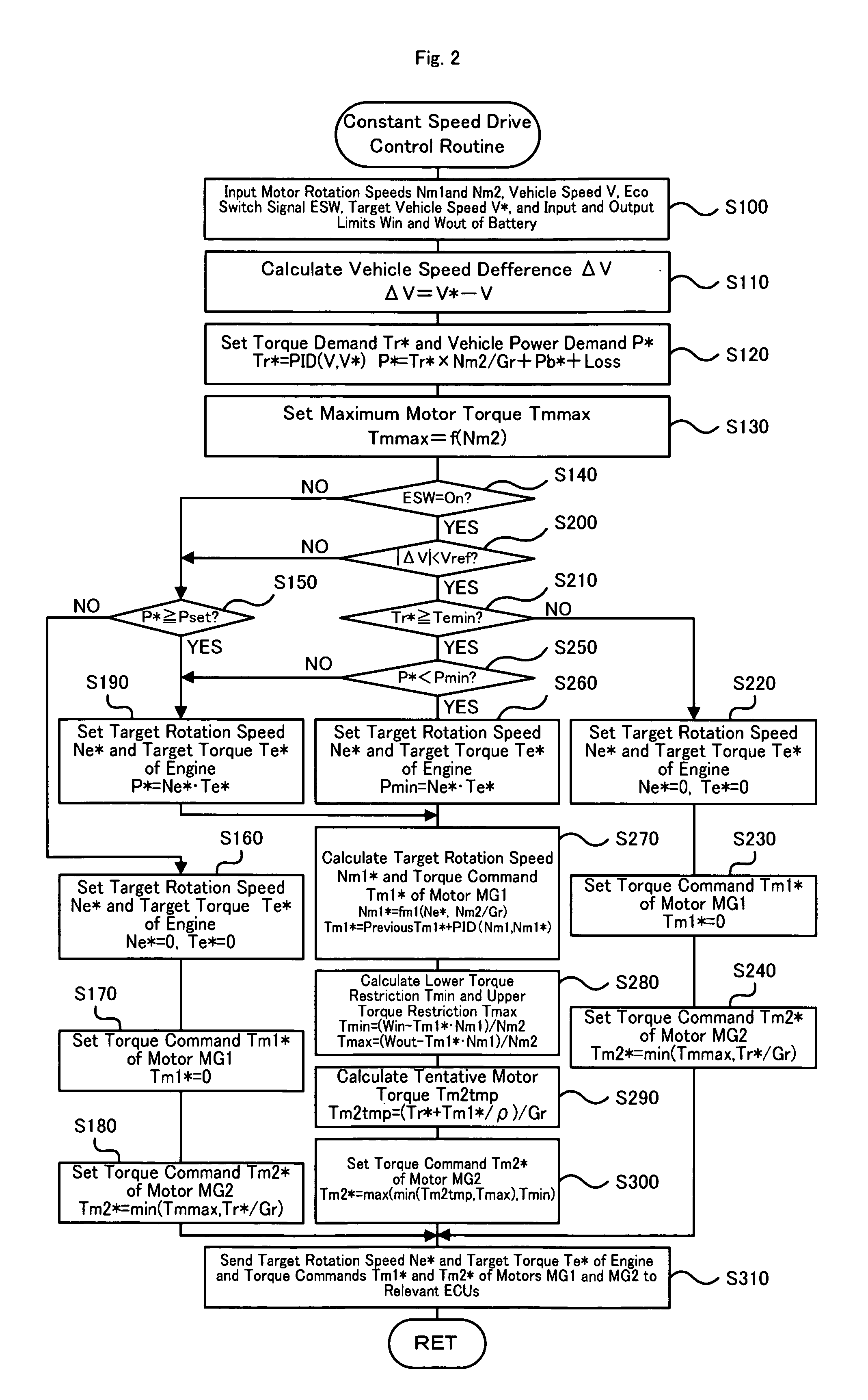
[0067] After the data input, the CPU 72 calculates the difference (vehicle speed difference) ΔV between the input target vehicle speed V* and the current vehicle speed V (step S410). In order to cancel out the calculated vehicle speed difference ΔV, the CPU 72 calculates the torque demand Tr* to be output to the ring gear shaft 32a or the driveshaft linked to the drive wheels 63a and 63b as the torque required for the hybrid vehicle 20 according to Equation (1) given above, while computing the vehicle power demand P* required for the hybrid vehicle 20 from the calculated torque demand Tr* (step S420). The maximum motor torque Tmmax possibly output from the motor MG2 is set corresponding to the rotation speed Nm2 of the motor MG2 (step S430). The processing flow of steps S410 to S430 is identical with the processing flow of steps S110 to S130 in the constant speed drive control routine of the first embodiment shown in the flowchart of FIG. 2.

[0068] The CPU 72 then checks the setting ...

second embodiment

[0075] As described above, in the case of the on setting of the eco switch signal ESW, when the vehicle power demand P* is not greater than the good fuel consumption-assuring minimum power Pmin, the hybrid vehicle 20B of the second embodiment drives the engine 22 at the drive point in the good fuel consumption range among the drive points on the optimum fuel consumption operation curve to ensure output of the required torque for the constant speed drive. Such control enhances the fuel efficiency for the constant speed drive. The engine 22 is driven at the drive point in the good fuel consumption range only when the vehicle speed V is not close to the target vehicle speed V*. This arrangement satisfies both the enhanced fuel efficiency and the smooth constant speed drive. The engine 22 is driven at the drive point in the good fuel consumption range only when the state of charge (SOC) of the battery 50 is in the range of the lower threshold value S1 and the upper threshold value S2. T...


PUM


Abstract

In the case of the on setting of an eco switch signal ESW, when a torque demand Tr* is less than a good fuel consumption-assuring minimum torque Temin, the hybrid vehicle of the invention stops the operation of an engine and controls a motor MG2 to output a required torque for constant speed drive. When the torque demand Tr* is not less than the good fuel consumption-assuring minimum torque Temin, on the other hand, the engine is driven at a drive point in a good fuel consumption range among drive points on an optimum fuel consumption operation curve to ensure output of the required torque for the constant speed drive. Such control enhances the fuel efficiency for the constant speed drive.

Description

BACKGROUND OF THE INVENTION [0001] 1. Technical Field [0002] The present invention relates to a hybrid vehicle and a control method of the hybrid vehicle. [0003] 2. Description of the Related Art [0004] One proposed constant speed drive technique for automobile performs acceleration control to maximize the fuel economy against the throttle opening in response to the driver's on operation of a fuel economy drive mode selection switch (see, for example, Japanese Utility Model Laid-Open Gazette No. S63-85533). Another proposed constant speed drive technique for automobile sets an upper limit of engine rotation speed in response to selection of a fuel economy mode (see, for example, Japanese Patent Laid-Open Gazette No. 2003-343305). One proposed technique for the enhanced fuel efficiency on an upload drive specifies a maximum fuel efficiency vehicle speed in a range of +10 km / h from a tentative target vehicle speed and sets the specified maximum fuel efficiency vehicle speed to the tar...

Claims


Application Information

Patent Timeline
IPC IPC(8): H02P17/00B60K31/00F02D29/02
CPCB60K1/02Y10T477/675B60K6/40B60K6/445B60K6/52B60K2006/262B60L11/12B60L15/2045B60L2220/52B60W10/06B60W10/08B60W20/00B60W30/182F02D29/02F02D31/001F02D41/0205Y02T10/52Y02T10/6265Y02T10/6286Y02T10/641Y02T10/7077Y02T10/7283Y02T10/6239Y10T477/679Y10T477/33B60K6/365Y02T10/72Y02T10/84B60L50/15Y02T10/40Y02T10/62Y02T10/64Y02T10/7072B60W20/11B60K6/448
Inventor YAMANAKA, AKIHIROONISHI, YUKIOYASUDA, TAKESHIITANO, HIDEO
Owner TOYOTA JIDOSHA KK
Why Eureka
Try Eureka