Locking system and flooring board

a technology of locking system and flooring board, which is applied in the field of locking system to achieve the effect of rational manufacturing and considerable improvement of tolerance of vertical fi

Inactive Publication Date: 2008-01-03
VÄLINGE INNOVATION AB
View PDF55 Cites 174 Cited by
  • Summary
  • Abstract
  • Description
  • Claims
  • Application Information

AI Technical Summary

Benefits of technology

[0052] A locking system according to the invention, however, can exhibit, both during the final inwards angling and in the joined state, a space in the groove under the tongue. Thanks to this space, the tongue can unimpededly be angled into the groove when two boards are joined by being angled together. Moreover, the locking system can be so designed that the angling together can take place while the boards are held in mutual contact at the upper corner portions of the adjacent joint edges. Despite the provision of this space in the groove under the tongue, it is according to the invention possible to achieve an exact vertical fit between tongue and groove in the joined state thanks to the fact that the lower abutment surfaces are, at least in large part, horizontally displaced outside the upper abutment surfaces.
[0053] The present invention solves, at the same time, the problem of undesirable backwards angling of the boards thanks to the lower abutment surfaces being displaced relative to the upper abutment surfaces in the direction of the locking element. In the known locking systems, it is only the rigidity of the projecting portion that limits the backwards angling. In the invention, however, said displacement accomplishes an angular limitation of the movement of the tongue that effectively counteracts any angling of the tongue past its intended position in the groove, i. e. that counteracts backwards angling of the boards.
[0054] The invention also presents the advantage that manufacture can be carried out with working tools which operate only in the plane of the floorboa

Problems solved by technology

There are today no known products or methods which result in sufficiently good solutions to the problems, requirements and desiderata stated below and related to (i) manufacture of floorboards with mechanical locking systems of the type stated, (ii) handling and laying of such floo

Method used


Image

  • Locking system and flooring board
  • Locking system and flooring board
  • Locking system and flooring board

Examples


Embodiment Construction

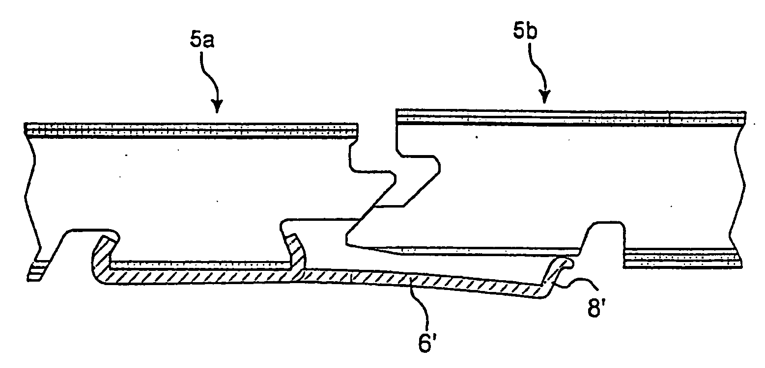
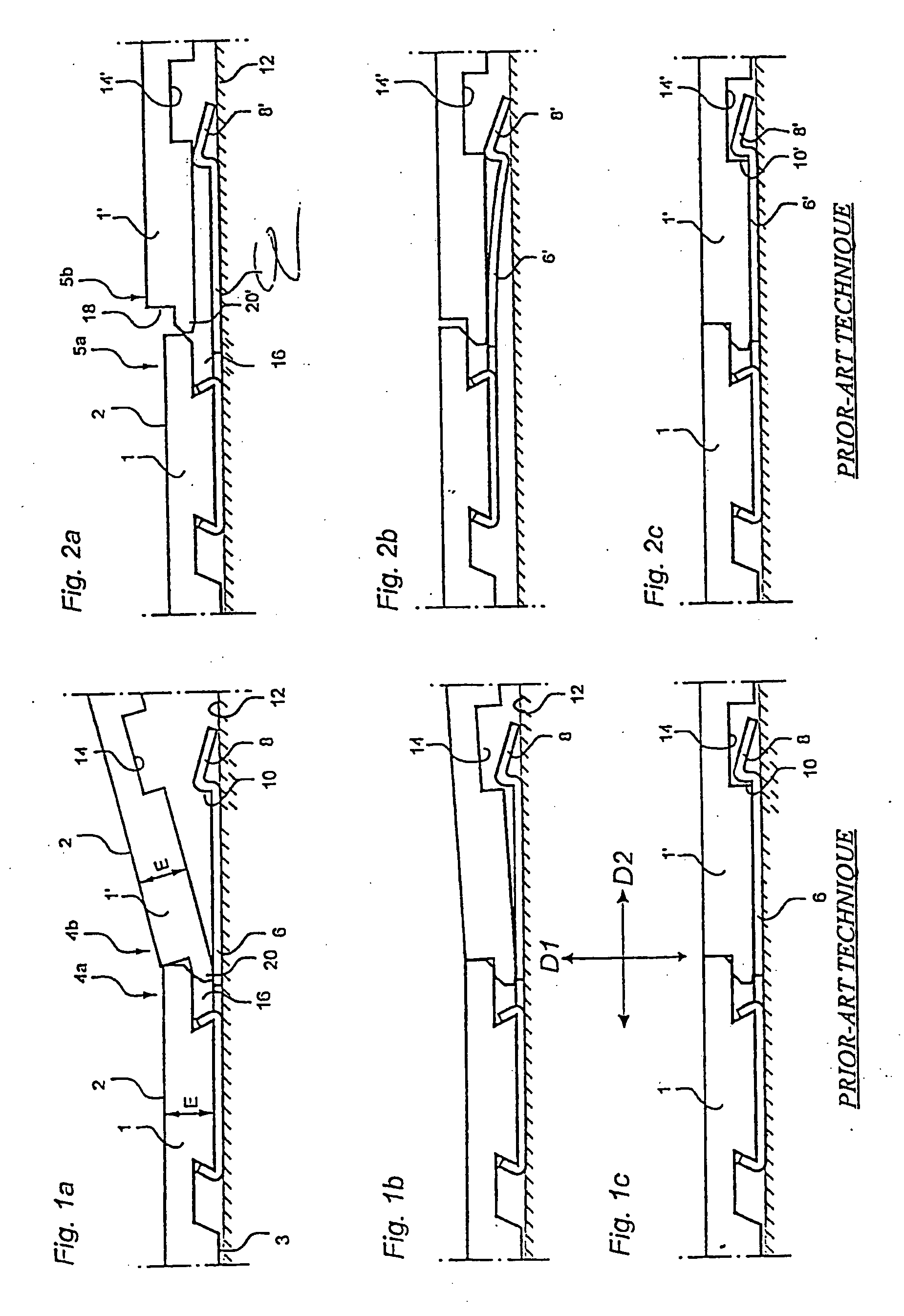
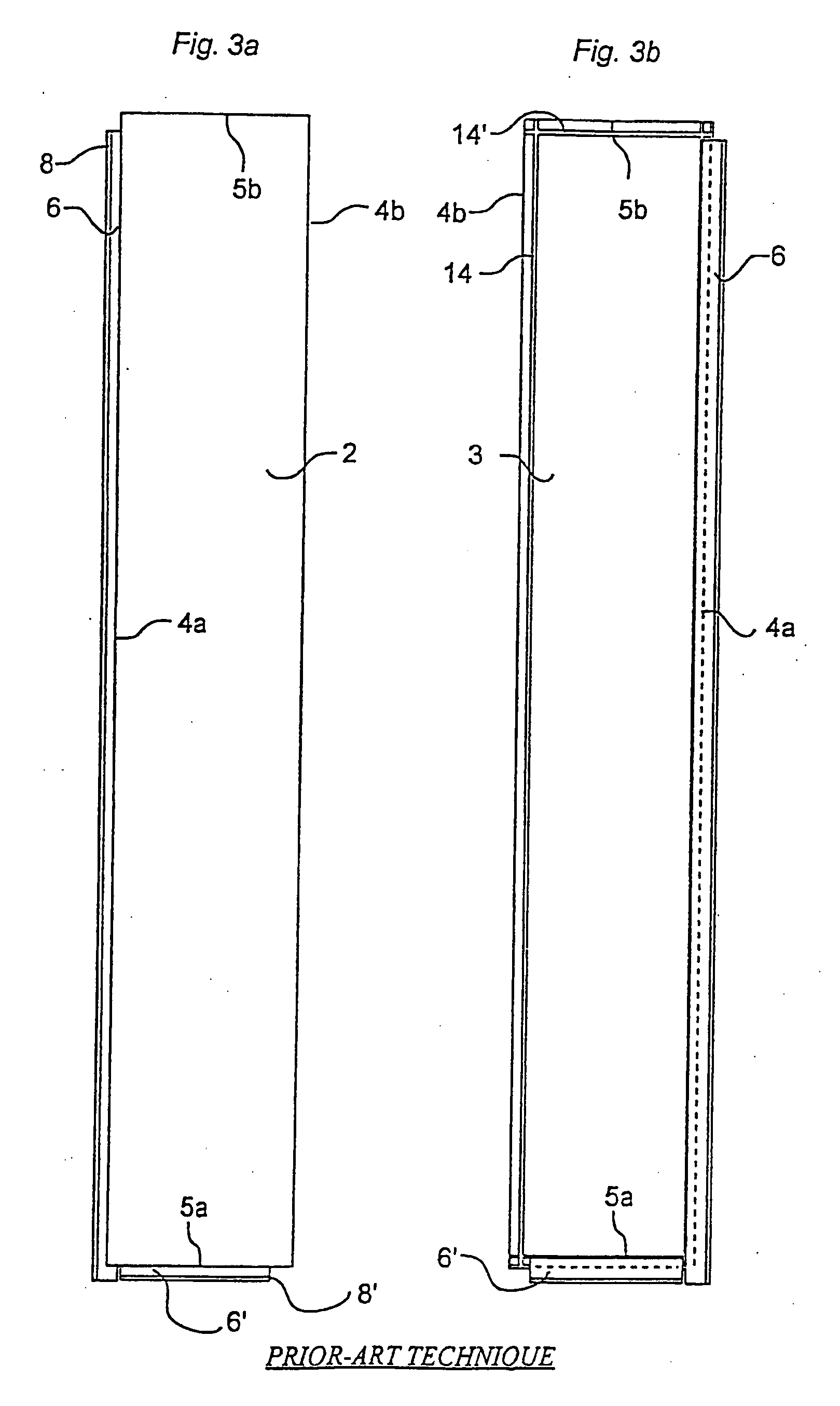
[0076] A first preferred embodiment of a floorboard 1 provided with a locking system according to the invention will now be described with reference to FIGS. 4-7. FIG. 4 is a sectional view of a long side 4a of the board 1, and also part of a long side 4b of an adjacent board 1.

[0077] The body of the board 1 consists of a core 30 of, for instance, wood fibre, which supports a top laminate 32 on its front side and a balance layer 34 on its rear side. The board body 30-34 is rectangular with long sides 4a, 4b and short sides 5a, 5b. A separate strip 6 with a formed locking element 8 is mounted at the factory on the body 30-34, so that the strip 6 constitutes an integrated part of the completed floorboard 1. In the Example shown, the strip 6 is made of resilient aluminum sheet. As an illustrative, non-limiting example, the aluminum sheet can have a thickness in the order of 0.6 mm and the floorboard a thickness in the order of 7 mm. For additional description of dimensions, possible m...


PUM


Abstract

A locking system for mechanical joining of floorboards. For horizontal mechanical joining there is a projecting portion with a locking element which cooperates with a locking groove in an adjacent board. A tongue-and-groove joint for vertical mechanical joining has cooperating upper abutment surfaces and cooperating lower abutment surfaces which are essentially parallel with the principal plane of the floorboards and of which the lower abutment surfaces are positioned essentially outside the outer vertical plane, i.e. displaced relative to the upper abutment surfaces. The tongue is movable at an angle into the groove and the locking element is insertable into the locking groove by mutual angular movement of the boards about the joint edges.

Description

CROSS-REFERENCE TO RELATED APPLICATIONS [0001] The present application is a continuation of U.S. Ser. No. 09 / 714,514, filed Nov. 17, 2000, which is a continuation of PCT International Application No. PCT / SE99 / 00933, filed May 31, 1999, and which designed the United States, and which claims the priority of SE 9801987-0, filed Jun. 3, 1998. U.S. Ser. No. 09 / 714,514, PCT International Application No. PCT / SE99 / 00933, and SE 9801987-0 are hereby incorporated herein by reference.FIELD OF THE INVENTION [0002] The invention generally relates to a locking system for mechanically joining floorboards. More specifically, the invention concerns an improvement of a locking system of the type described and shown in WO 94 / 26999. The invention also concerns a floorboard provided with such a locking system. [0003] It is known that board material can be joined mechanically and that there are many different types of joining systems. The present invention suggests specifically how a modified tongue-and-...

Claims


Application Information

Patent Timeline
IPC IPC(8): E04B5/02E04F15/00E04F15/02E04F15/04
CPCE04F15/02E04F15/04E04F2201/025E04F15/02044E04B5/00E04F15/02038E04F2201/0517
Inventor PERVAN, DARKO
Owner VÄLINGE INNOVATION AB
Why Eureka
Try Eureka