[0015] Since the
cooling capacity is controlled to compensate for future changes in the cooling demand in contrast to the traditional systems wherein the compressing capacity is controlled based on an actually needed cooling capacity, a better control with less changes to the compressing capacity can be achieved. Since each change in the capacity implies wear on the compressing unit, the invention further facilitates a more economical operation of the system. Depending upon the implementation, one
advantage of the invention could be that it facilitates a non-causal reaction to set-point changes and disturbances. Where a traditional, e.g. PID based, control approach in refrigeration systems reacts on disturbances when they occur, a system according to the present invention employ estimates of future disturbances to optimize the control action. Hence the controller can react to disturbances before they occur and thereby reduce the effects of the disturbances. Another
advantage over PID based control could be the ability to compensate for saturations, such as a maximum compressor capacity. If future saturation is predicted, the controller can adjust the pre-saturated control action to compensate for the future saturation. This enables an optimal sequence of control actions, also referred to as a trajectory of actions, taking the saturations into account. In practice, the refrigerated space may be cooled to a temperature which is lower than an actually desired set-point temperature in order to compensate for a predicted future cooling demand which exceeds the available cooling capacity of the system.
[0016] The cooling capacity may be controlled by controlling at least one of the compressing capacity and the
mass flow through the evaporators. The compressing capacity could be controlled e.g. in discrete steps by switching a compressor on or off, or the compressing capacity could be controlled by varying the displacement performed by the compressing unit(s), e.g. by varying the rotational speed of a
piston or
scroll compressor. The
mass flow could be varied via an
inlet valve controlling the flow through the
evaporator.
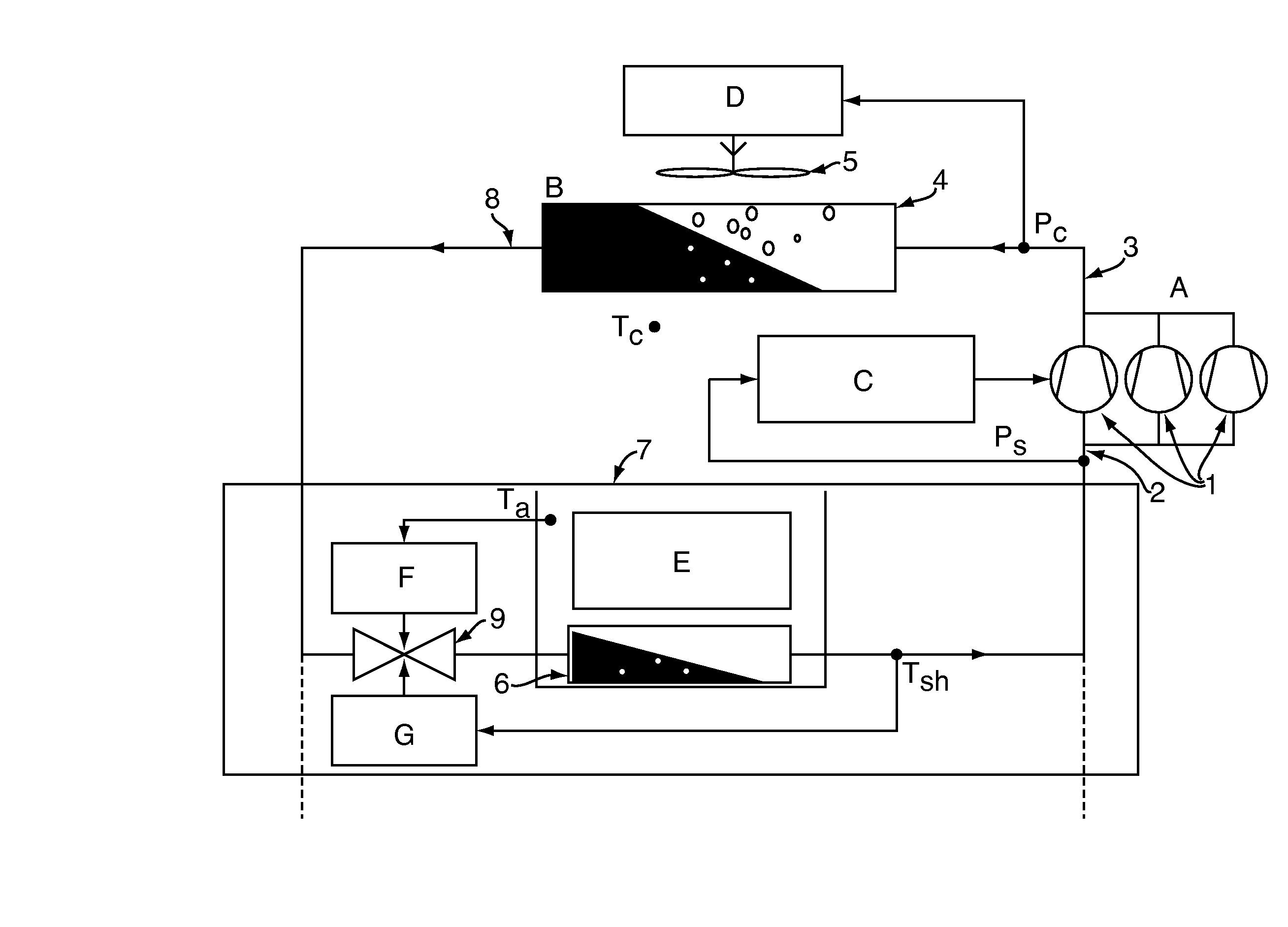
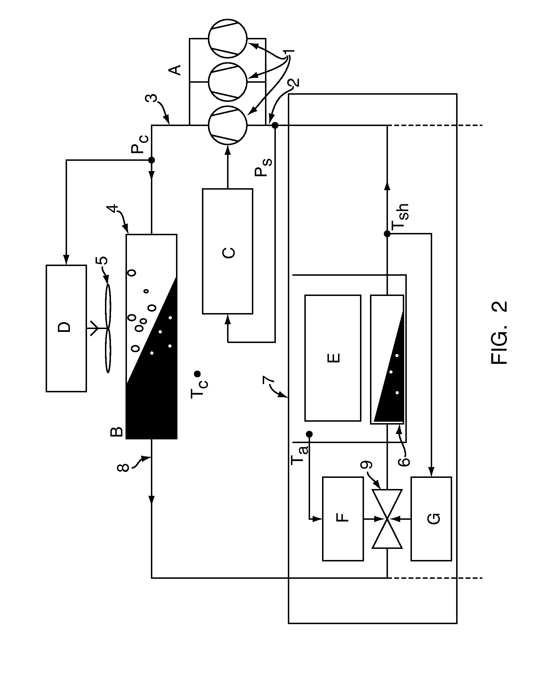
[0017] During filling of the evaporator, the flow of the refrigerant is preferably controlled to achieve a minimum superheat region. For this purpose, a thermostatic expansion valve or an electronically controlled valve is inserted e.g. in an inlet of the evaporator. The evaporator will produce the maximum cooling capacity for the given operation condition. The temperature of the secondary fluid of the refrigerated space is controlled e.g. by a
hysteresis control which switches said filling control on and off to keep the
air temperature within the desired temperature band. For a fixed value of the compressing capacity and flow of refrigerant, the cooling capacity depends on the
temperature difference between the evaporating temperature and the temperature of the secondary fluid. The compressor control affects the operation conditions by controlling the suction pressure to achieve a desired
evaporation temperature. Hence, the objective of the compressor control is to achieve a suction pressure that produces an evaporating temperature that enables the system to meet the cooling demands. If the evaporating temperature is too close to the temperature of the secondary fluid, the system cannot meet the cooling demand. A too low evaporating temperature is undesirable because the compressor uses more energy than necessary because the
pressure difference between the inlet and outlet is increased.
[0018] The estimated future cooling demand could be comprised in a
mathematical model which gives the cooling estimate based on a time of the day, or the cooling estimate could be logged in a table, e.g. with corresponding values of time and estimated demand, e.g. for an hour, a day, or a year. A prediction of future cooling demands can be established in different ways. Examples are:
[0019] by observing past changes in cooling demands. This can be done by estimating the
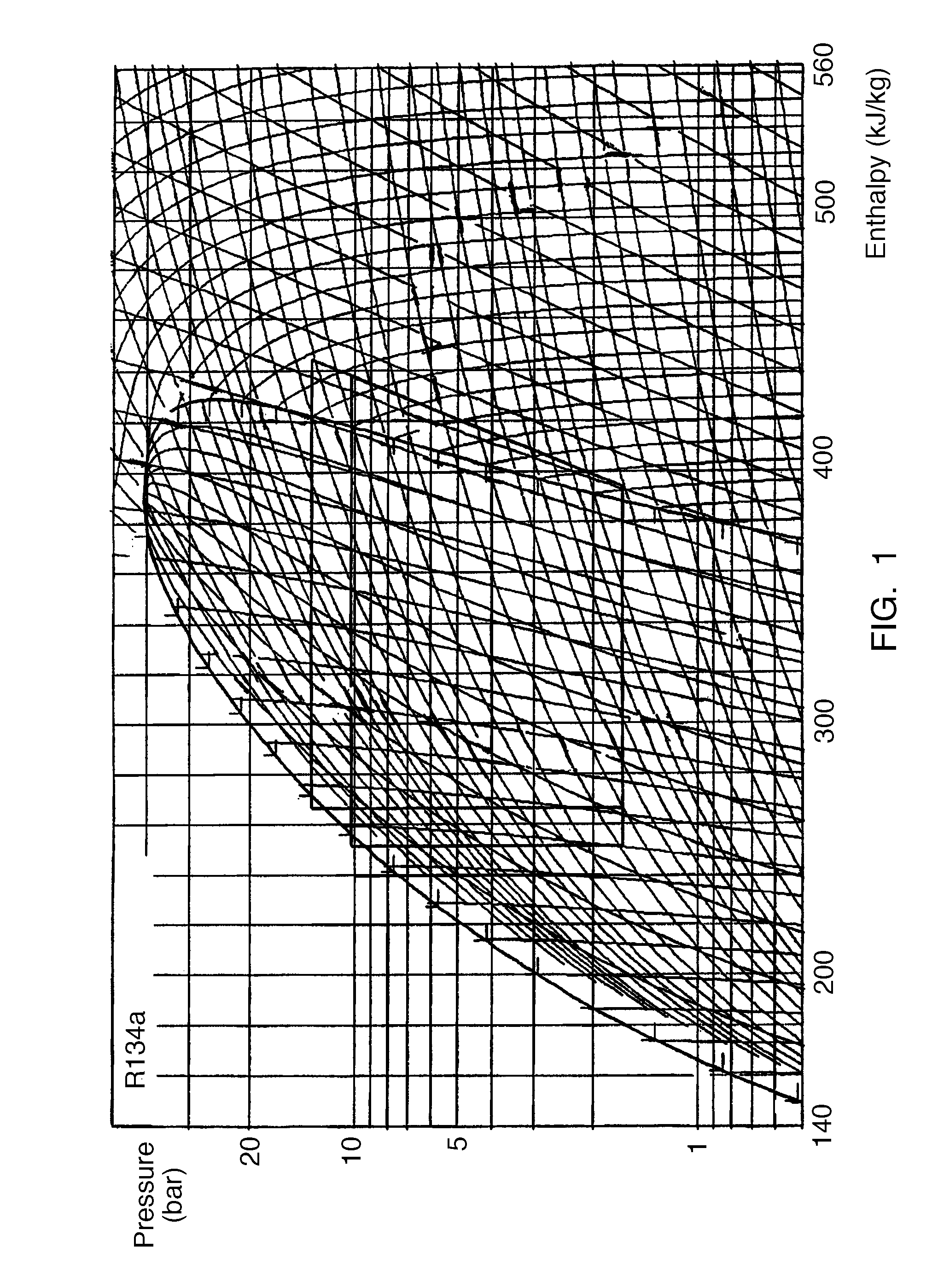
mass-flow of refrigerant through the compressor by using the suction pressure and compressor capacity as input to a model of the refrigeration system. Calculating the inlet and outlet specific
enthalpy can be done by using
temperature and pressure as input to a refrigerant specific
enthalpy function. Future cooling demands can then be predicted based on the past values. This will enable capturing of demand variations during a 24 hour, a weekly, or a yearly cycle.
[0020] by
logging past measurement of physical entities such as the temperature of the spaces in which the refrigeration system is installed, e.g. the temperature of a supermarket. From said logged values, a model of how the physical entities influence the cooling demands can be established. Using the model and predictions of the physical entities, the future cooling demands can be predicted.

