Variable speed wind power generation system

a technology of wind power generation and variable speed, which is applied in the direction of electric generator control, machines/engines, mechanical equipment, etc., can solve the problems of insufficient reactive generation power amount and and achieve the effect of reducing the effect of voltage fluctuation in the power system

Active Publication Date: 2008-01-03
HITACHI IND PROD LTD
View PDF8 Cites 50 Cited by
  • Summary
  • Abstract
  • Description
  • Claims
  • Application Information

AI Technical Summary

Benefits of technology

[0051]According to the variable speed wind power generation system of the present invention, since the fluctuation of generated power to be outputted to a power system can be made smaller in comparison with the conventional torque control method, it is possible to reduce the effect on the voltage fluctuation of the power system.

Problems solved by technology

This causes voltage fluctuation in a power system of the wind power generation system.
With power factor control, since the reactive power output is small when the generated power is small, it may not be possible to obtain reactive generation power amount sufficient to suppress voltage fluctuation.

Method used


Image

  • Variable speed wind power generation system
  • Variable speed wind power generation system
  • Variable speed wind power generation system

Examples


embodiment 1

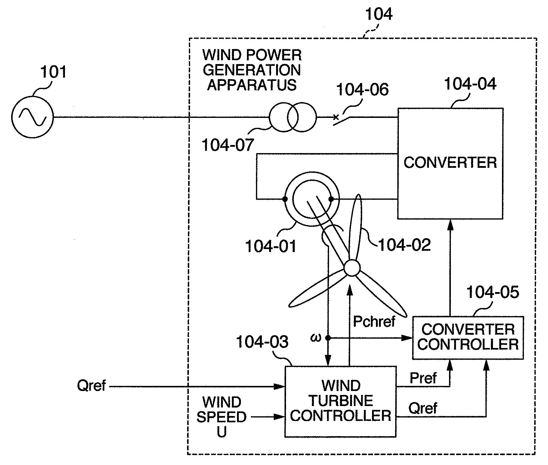
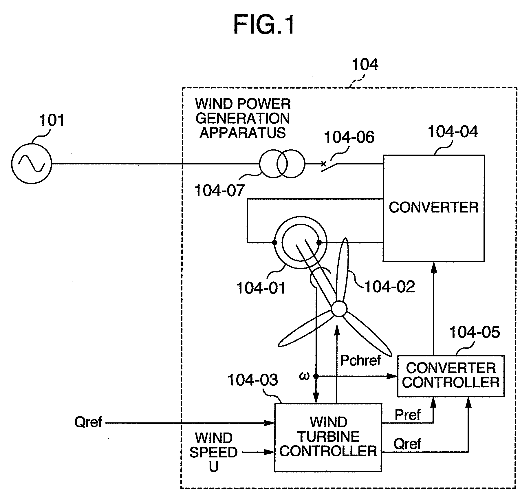
[0073]FIG. 1 is a single line diagram showing a system configuration according to an embodiment of the present invention. The configuration of a power system for electric power transmission will be explained below. Power generation equipment 101 of the power system can be simply considered as a power supply if it has a large capacity. The power from the power generation equipment 101 of the power system is transmitted to homes, buildings, factories, etc. via power lines.

[0074]A wind power generation apparatus 104 is connected to the power lines through a transformer 104-07 for coupling with the power system.

[0075]The wind power generation apparatus 104 includes mainly a wound-rotor induction generator 104-01, blades 104-02, a wind turbine controller 104-03, a converter (excitation apparatus) 104-04, and a converter controller 104-05.

[0076]The blades 104-02 are mechanically connected to the rotor of the generator 104-01 (through gears or the like). The rotor winding of the generator ...

embodiment 2

[0139]Another embodiment will be explained below with reference to FIGS. 6-8. The same symbols are assigned to elements having the same function as those in Embodiment 1, and duplicated explanations are omitted. Embodiment 2 uses a different method for creating an active power command Pref from that in Embodiment 1.

[0140]FIG. 6 shows the efficiency with which the wind turbine produces energy from wind. The horizontal axis indicates the ratio of the circumferential speed Vp1 [m / s] of a blade (end) relative to the wind speed U [m / s] (circumferential speed ratio X=Vp1 / U), and the vertical axis indicates the efficiency. As clearly shown in the FIG. 6, the efficiency is maximized at a certain circumferential speed ratio λ. The above-mentioned pitch angle table can be realized, for example, by obtaining in advance a pitch angle (at which rotating speed for a circumferential speed ratio with high efficiency can be obtained) from each wind speed value based on the characteristics in FIG. 7 ...

embodiment 3

[0148]Still another embodiment will be explained below with reference to FIGS. 9 and 10. FIG. 9 shows another embodiment of the wind turbine controller shown in FIG. 7. The same symbols are assigned to elements having the same function as those in Embodiment 1, and duplicated explanations are omitted.

[0149]The wind turbine controller 104-03 will be explained below with reference to FIG. 9. The wind turbine controller 104-03 inputs the wind speed U and detects an average wind speed Uav using a first order lag filter LPF or the like. The detected average wind speed Uav is input to the speed command calculating unit SCAL and power command calculating unit PREFCAL.

[0150]The power command calculating unit PREFCAL calculates an active power command value Pref using, for example, a table of average wind speed Uav relative to output power. As shown in the above-mentioned embodiment in FIG. 5, the power command calculating unit PREFCAL can be realized by obtaining in advance a table of power...


PUM


Abstract

A variable speed wind power generation system including a wind turbine, generation power command means for generating a generation power command value based on a state quantity of the wind turbine and generator control means for controlling the power converter for controlling electric power of the generator, wherein the generator control means operates to regulate the generation power of the generator in order to change the generation power amount according to the generation power command value.

Description

CROSS-REFERENCE TO RELATED APPLICATION[0001]The present application relates to subject matters described in a co-pending patent application serial No. ______ to be filed on May 25, 2007 entitled “WIND POWER GENERATION APPARATUS, WIND POWER GENERATION SYSTEM AND POWER SYSTEM CONTROL APPARATUS” by Masaya Ichinose, et al. and assigned to the assignees of the present application.BACKGROUND OF THE INVENTION[0002]The present invention relates to a wind power generation system with variable rotating speed of a generator.[0003]A wind power generation apparatus receives wind energy on its blades and then converts it into rotational energy to generate rotational torque at a rotor of a generator. The wind power generation apparatus produces electric power from wind-induced torque by generating a magnetic field at the rotor (or stator or both of them). It supplies the produced electric power to a power system or load through electric wires.[0004]Since a wind power generation system utilizes win...

Claims


Application Information

Patent Timeline
Patent Type & Authority Applications(United States)
IPC IPC(8): H02P9/04
CPCF03D7/0224F03D7/0272F03D7/043F05B2270/309F05B2270/32H02P2101/15F05B2270/328H02P9/007Y02E10/723Y02E10/725F05B2270/327Y02E10/72
Inventor ICHINOSE, MASAYAOOHARA, SHINYAFUTAMI, MOTOOSODEYAMA, TADASHIIMAIE, KAZUHIRO
Owner HITACHI IND PROD LTD
Why Eureka
Try Eureka