
Cylindrical lens-based light sensor and use of the sensor in an automated method and apparatus for monitoring a target fluid for contaminants

a technology of light sensor and cylindrical lens, which is applied in the direction of instruments, measurement devices, scientific instruments, etc., can solve the problems of high cost of signal processing computation power, lack of spatial extent of detector,

Inactive Publication Date: 2008-01-03
PHYSICAL SCI
View PDF2 Cites 18 Cited by
  • Summary
  • Abstract
  • Description
  • Claims
  • Application Information

AI Technical Summary

Benefits of technology

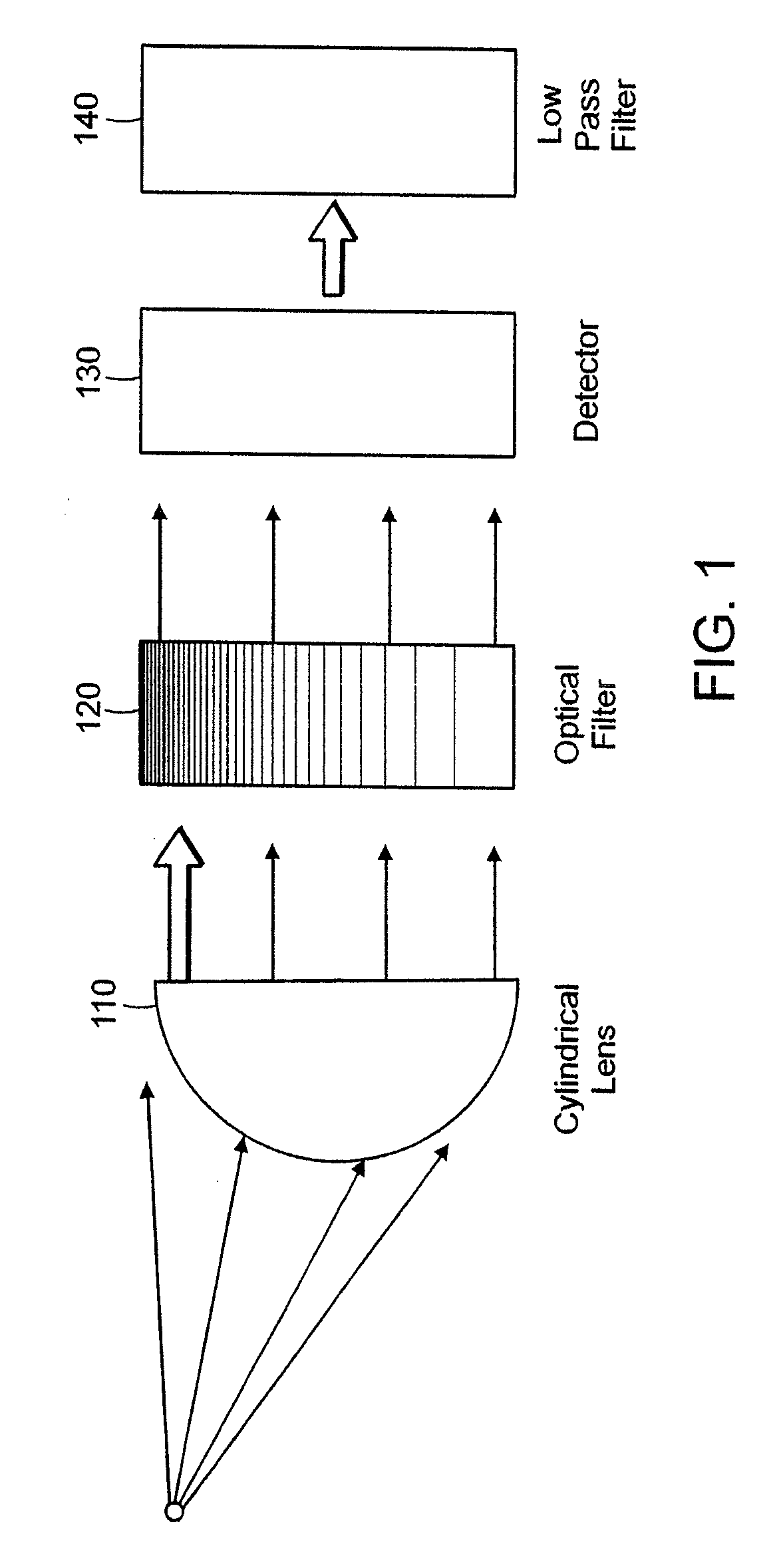
[0009] In particular embodiments, the cylindrical lens focuses the scattered light within a range of scattering angles such that the various scattering angles are mapped into vertical spatial bands at the detector. Preferably, the detector generates a video output of the bands. By virtue of this mapping of scattering angles to vertical bands, each pixel column of the video output converts directly to a given scattering angle, simplifying image analysis. A benefit of using a cylindrical lens is that commercial, rectangular Charge-Coupled Device (CCD) detectors can be used for significant savings in cost and manufacture complexity.
[0011] Particular embodiments of the cylindrical lens-based light sensor can further include an optical filter disposed between the cylindrical lens and the linear detector, such that the optical filter can attenuate the intensity of the received light according to scattering angle or the intensity of the received light within regions in which the focused light deviates from alignment along substantially parallel lines. A benefit of such filtering is an increase in the range of light intensities that can be detected by the sensor.
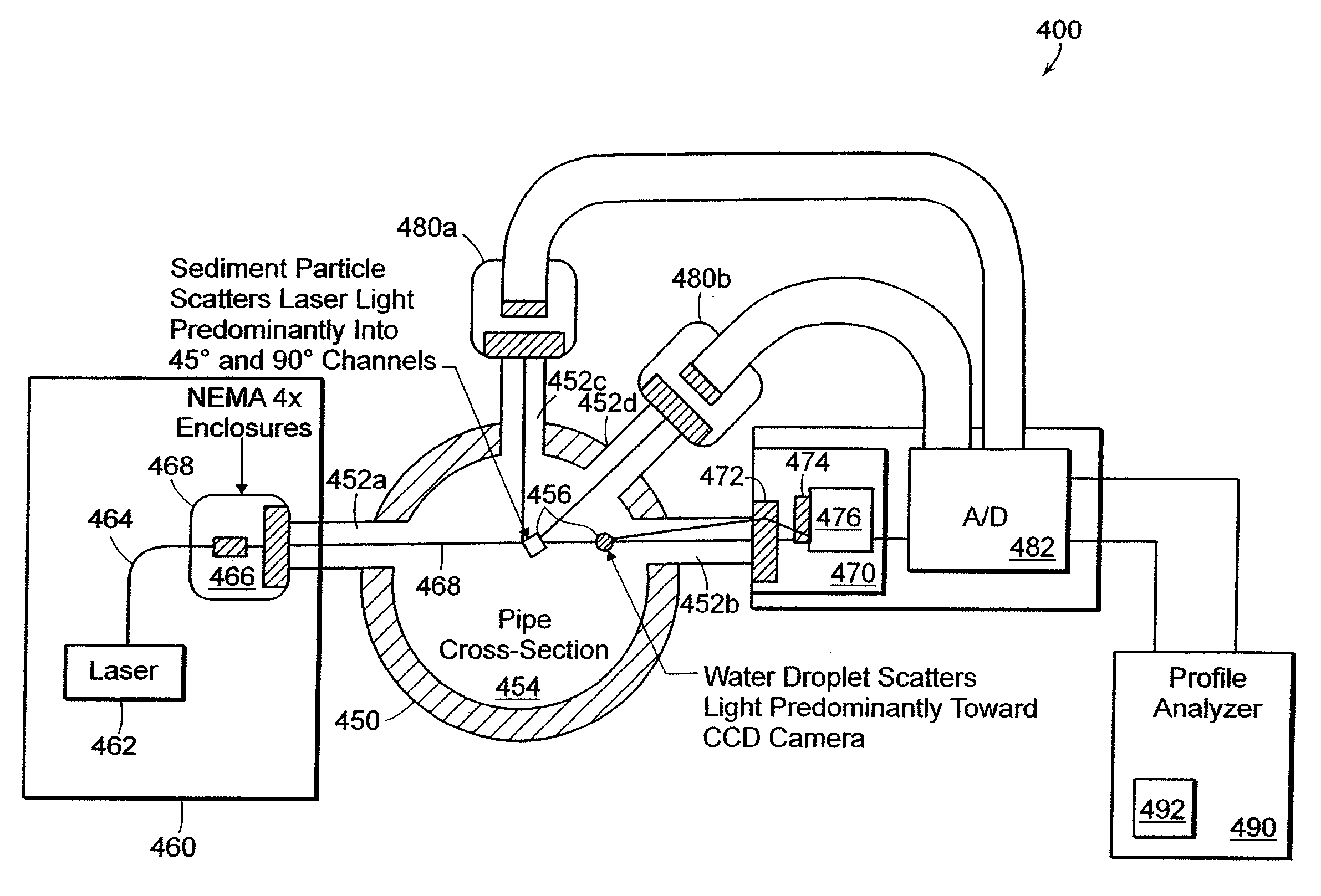
[0014] For example, in military aircraft carriers, complex fuel distribution systems are installed for the purpose of refueling aircraft. Contaminated fuel has been known to cause engine failure, resulting in unnecessary repair work and delayed flights. Even very small quantities of dirt or solid matter can plug or restrict fuel metering orifices and accelerate the clogging of fuel filters.
[0017] The first light sensor can further include an optical filter disposed between the cylindrical lens and the linear detector, such that the optical filter can attenuate the intensity of the received light according to scattering angle or the intensity of the received light within regions in which the focused light deviates from alignment along substantially parallel lines.

Problems solved by technology

This method often suffers from the lack of spatial extent of the detector to reduce noise through averaging.
This method often suffers from the high cost of signal processing computation power.

Method used


Image

  • Cylindrical lens-based light sensor and use of the sensor in an automated method and apparatus for monitoring a target fluid for contaminants
  • Cylindrical lens-based light sensor and use of the sensor in an automated method and apparatus for monitoring a target fluid for contaminants
  • Cylindrical lens-based light sensor and use of the sensor in an automated method and apparatus for monitoring a target fluid for contaminants

Examples


Embodiment Construction

[0035] According to one aspect of the invention, a light scattering sensor is provided with a cylindrical lens focusing received light along substantially parallel lines, or bands, that correspond to a range of scattering angles and a linear detector that detects the light intensity along the substantially parallel lines. By using a cylindrical lens, the lens serves as an auto-collimator, whereby light scattered at a specific angle from the collimated light beam strikes the linear detector at a corresponding specific location regardless of the location from where the light was scattered.

[0036]FIG. 1 is a schematic diagram of a cylindrical lens-based, light scattering sensor according to one embodiment. The light scattering sensor 100 includes a cylindrical lens 110, an optical filter 120, a linear detector 130 and a low-pass filter 140. The cylindrical lens 110 is preferably positioned one focal length in front of the detector 130 and serves as an auto-collimator, whereby light sca...


PUM

PropertyMeasurementUnit
sizeaaaaaaaaaa
concentrationaaaaaaaaaa

Abstract

A light scattering sensor is provided with a cylindrical lens focusing received light along substantially parallel lines, or bands, that correspond to a range of scattering angles and a linear detector that detects the light intensity along the substantially parallel lines. By using a cylindrical lens, the lens serves as an auto-collimator, whereby light scattered at a specific angle from the collimated light beam strikes the linear detector at a corresponding specific location regardless of the location from where the light was scattered. Embodiments of the cylindrical lens-based light sensor can be applied to a number of different applications and industries that analyze light scattering intensity as a function of scattering angle. For example, embodiments of the cylindrical lens-based light scattering sensor can be used for monitoring a target fluid for contaminants.

Description

GOVERNMENT RIGHTS [0001] The government may have certain rights in the invention under Contract No. N68335-00-C-0384 from the United States Department of the Navy.FIELD OF INVENTION [0002] The present invention generally relates to light scattering measurements and processes in which the scattering behavior of particles or index of refraction variations between an optical source and a detector as a function of angle is required. [0003] More particularly, the present invention relates to a light sensor having cylindrical optics to obtain high angular resolution of light scattering within an extended dynamic range and methods of using the sensor in applications that analyze light scattering intensity as a function of scattering angle. BACKGROUND [0004] The acquisition of light scattering profiles as a function of angle is a critical part of certain measurement devices used in many laboratory and industry settings. Typically, particle sizing devices for laboratory use in the various sc...

Claims


Application Information

Patent Timeline
Patent Type & Authority Applications(United States)
IPC IPC(8): G01N21/00
CPCG01N21/51G01N2021/4711G01N2021/4707G01N21/532
Inventor WHITE, MICHAEL A.TEMPLEMAN, CHRISTOPHER L.FRISH, MICHAEL B.NEBOLSINE, PETER E.
Owner PHYSICAL SCI
Learn More