Rotary pulser

Active Publication Date: 2008-01-03
SAWAFI AL JAZEERA OILFIELD PROD & SERVICES CO LTD
View PDF41 Cites 21 Cited by
  • Summary
  • Abstract
  • Description
  • Claims
  • Application Information

AI Technical Summary

Benefits of technology

[0016]It is an object of the present invention to obviate or mitigate at least one disadvantage of previous mud pulsers and pulse generators.
[0020]Preferably the position of the windowed restrictor is sensed when the mud flow through the flow passage is restricted, and wherein the amount and direction of rotations of the motor from that position are counted and stored by the controller. Preferably, the sensed position of the windowed restrictor is calibrated as the fully closed position of the windowed restrictor in controlling the windowed restrictor's travel during operation to avoid excess collision or frictional wear between the windowed restrictor and the windowed restrictor stop. Preferably the controller senses the position of the windowed restrictor by sensing whether movement of the windowed restrictor is impeded, and wherein the controller counts the number of rotations of the motor until the windowed restrictor is impeded and compares the number of rotations to an expected number of rotations to determine the position of the windowed restrictor with respect to the fixed housing. Preferably, the expected number of rotations is preset to allow a predetermined rate of mud flow past the windowed restrictor when the windowed restrictor is moved away from the fixed housing by the preset expected number of rotations.
[0021]Preferably, the controller includes a debris clearing command that is initiated when the number of rotations counted is not equal to the expected number of rotations. Preferably, the debris clearing command causes the motor to reciprocate the windowed restrictor to dislodge any debris present between the windowed restrictor and the fixed housing.
[0025]Preferably, the sensor is a mud flow sensor, pressure sensor, temperature sensor, rotation-step counter, position sensor, velocity sensor, current level sensor, battery voltage sensor, timer, or error monitor. Preferably, the memory is adapted to store time-stamped or counted sensed events together with an event-type indication. Preferably, the control circuitry is programmable to cause an action within the actuator responsive to a sensed event, a time, an elapsed time, a series of sensed events, or any combination thereof. Preferably, the operator interface provides information from memory to the operator. Preferably, the operator interface allows an operator to alter the programming of the control circuitry.

Problems solved by technology

Solenoid-type pulser actuators have also been used to actuate the main pulser valve, however, there are many problems with such a system.
Under drilling conditions requiring higher than normal mud flow, the limited pressures exerted by the solenoid may be unable to overcome both the pressure of the return spring and the increased pressure of the flowing mud, resulting in a failure to open the servo-valve, resulting in the main valve remaining in a position in which mud flow is not restricted, and therefore failing to communicate useful information to the surface.
A further problem with the use of a solenoid to actuate the pulser assembly is the limited speed of response and recovery that is typical of solenoid systems.
This delay results in a maximum data rate (pulse width) of approximately 0.8 seconds / pulse, limiting the application of the technology.
Therefore, inclusion of a solenoid within the tool adds complexity to the process of assembling and repairing the pulser actuator, and impairs the overall operability and reliability of the system.
Existing tools are also prone to jamming due to accumulation of debris, reducing the range of motion of the pilot valve.
Particularly when combined with conditions of high mud flow, the power of the solenoid is unable to clear the jam, and the tool is rendered non-functional.
The use of a stepper motor to directly control the main pulse valve, however, requires a large amount of electrical power, possibly requiring a turbine generator to supply adequate power to operate the system for any length of time downhole.
Repair of previous pulsers has been an as yet unresolved difficulty.
Typically, the entire tool has been contained within one housing, making access and replacement of small parts difficult and time-consuming.
Therefore, in order to dissemble the tool for repair, the bellows seal had to be removed, causing the integrity of the pressurized oil chamber to be lost at each repair.
Furthermore, a key area of failure of MWD pulser drivers has been the failure of the bellows seal around the servo-valve activating shaft, which separates the drilling mud from the internal oil.
In existing systems, the addition of a second seal is not feasible, particularly in servo-drivers in which the servo-valve is closed by a spring due to the limited force which may be exerted by the spring, which is in turn limited by the available force of the solenoid, and cannot overcome the friction or drag of an additional static / dynamic linear seal.

Method used


Image

  • Rotary pulser
  • Rotary pulser
  • Rotary pulser

Examples


Embodiment Construction

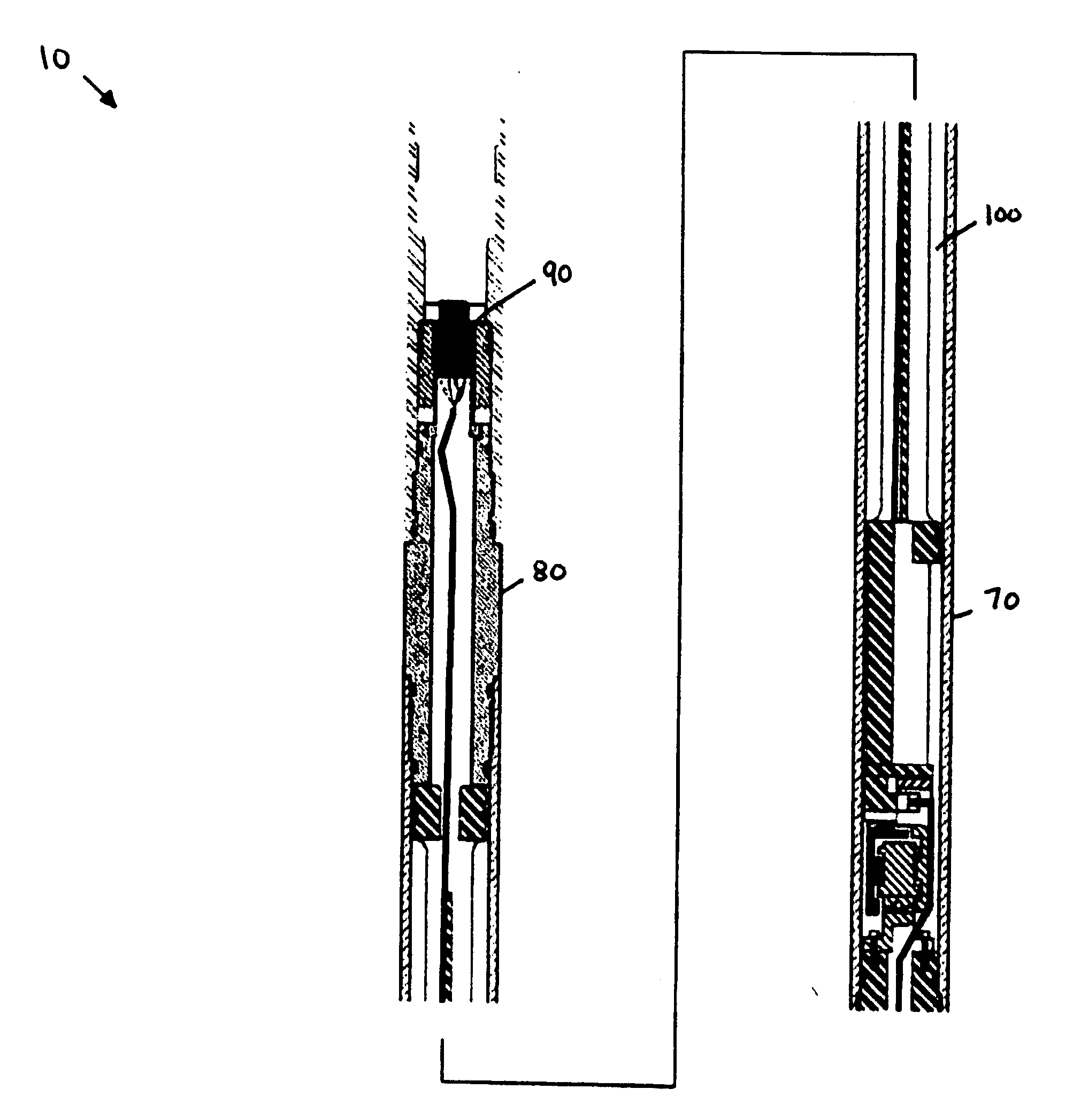
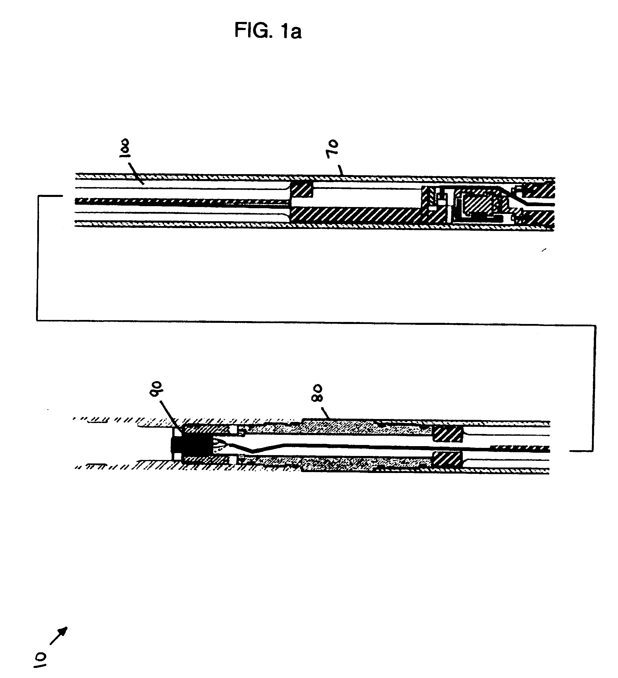
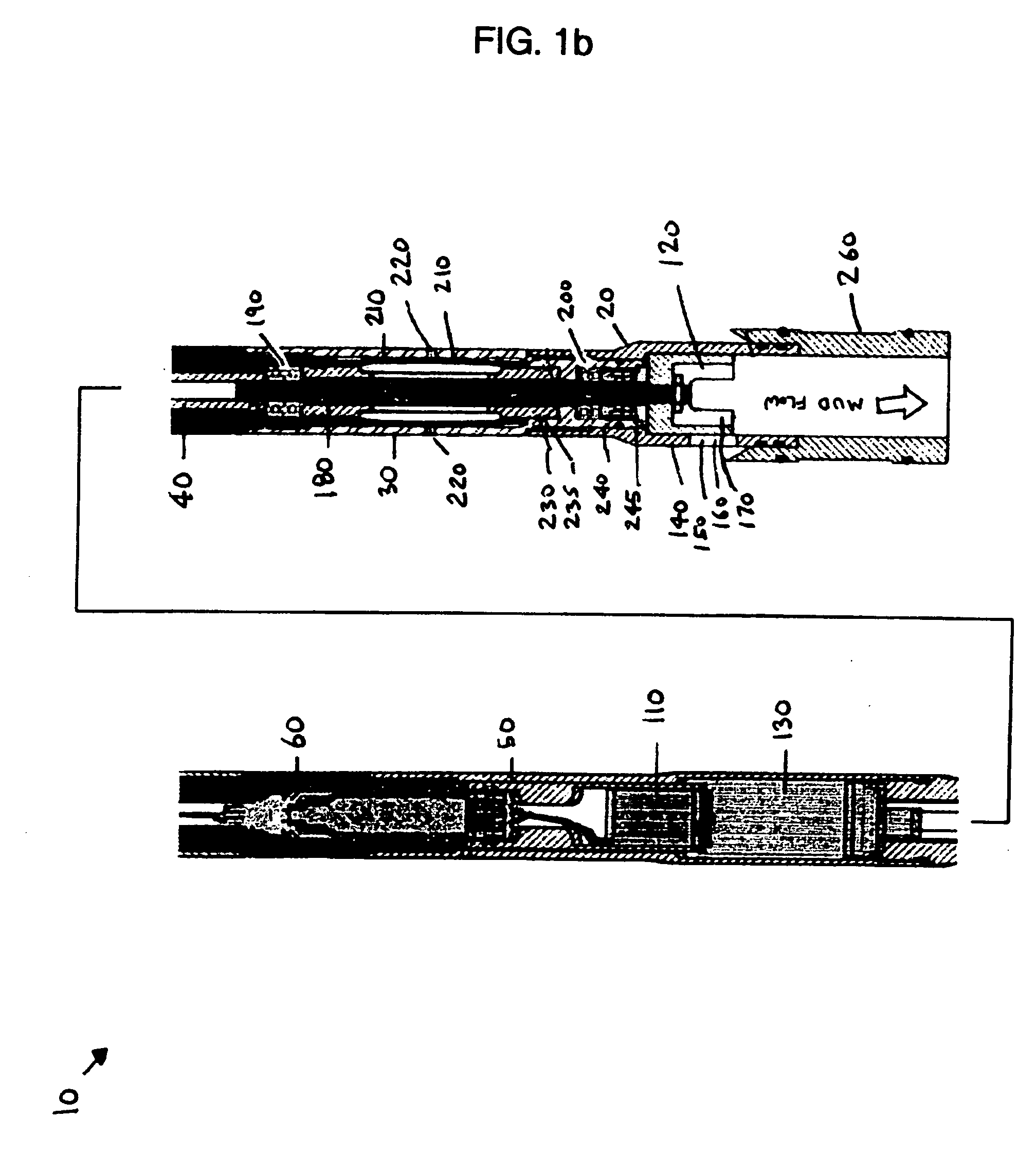
[0032]The present invention relates to an apparatus and method for actuating a mud pulser telemetry system used during well-drilling or well logging operations. The present apparatus allows a pulser valve to be powered both in opening (e.g. to allow generally unrestricted flow) and in closing (e.g. to generally restrict flow,) and does not rely on a solenoid system.

[0033]The powered opening and closing of a windowed restrictor results in various functional and economic advantages, including the ability to clear debris from the restricted portion of the mud flowpath, and faster data rates due to elimination of inherent operating delays in the solenoid systems of previous tools, with the end result of providing a pulser driver which consumes a minimal amount of power (e.g. DC or AC electricity) while providing more force with which to drive the windowed restrictor in each direction. Therefore, the pulser remains functional at a comprehensive range of downhole drilling conditions.

[0034...


PUM


Abstract

An improved energy efficient intelligent rotary pulser for generating a mud pulse in a MWD (measurement while drilling) application. In the rotary pulser, a control circuit activates a brushless motor that rotates a windowed restrictor relative to a fixed housing to act as a shutter and window respectively. Opening of the windowed restrictor allows generally unrestricted mud flow. Closing of the windowed restrictor generally restricts mud flow. The windowed restrictor is powered both in opening and closing operations by the motor.

Description

FIELD OF THE INVENTION[0001]The present invention relates generally to a telemetry system, and in particular to a measurement while drilling (MWD) system. More particularly, the present invention relates to an actuator for a downhole mud pulser for sending information from downhole to surface.BACKGROUND OF THE INVENTION[0002]The desirability and effectiveness of well logging systems where information is sensed in the well hole and transmitted to the surface through mud pulse telemetry has long been recognized. Mud pulse telemetry systems provide the driller at the surface with means for quickly determining various kinds of downhole information, most particularly information about the location, orientation and direction of the drill string at the bottom of the well in a directional drilling operation. During normal drilling operations, a continuous column of mud is circulating within the drill string from the surface of the well to the drilling bit at the bottom of the well and then ...

Claims


Application Information

Patent Timeline
IPC IPC(8): H04H9/00
CPCE21B47/187E21B47/18E21B47/24
Inventor PRATT, F. DALELAMBE, KENNETH A.
Owner SAWAFI AL JAZEERA OILFIELD PROD & SERVICES CO LTD
Why Eureka
Try Eureka