Capillary system for controlling the flow rate of fluids

a fluid flow and capillary technology, applied in the field of microfluidic technology, can solve the problems of not being able to adapt to the needs of different users, unable to adapt to the needs of different applications and users, and not being flexible in technology

Inactive Publication Date: 2008-01-03
IBM CORP
View PDF0 Cites 36 Cited by
  • Summary
  • Abstract
  • Description
  • Claims
  • Application Information

AI Technical Summary

Benefits of technology

[0024]Yet another aspect of the present invention is preventing trapping of air in the capillary of microfluidic device.
[0027]Still another object of the present invention is eliminating the need of additional peripheral equipment for controlling the motion of liquid in the microfluidic device.

Problems solved by technology

An important limitation with assay technologies is that they address very different applications and different users.
This technology is not flexible and is not suited for typical assays in biology where multiple solutions and reagents must be employed for the assay.
Moreover, the pressure barrier should be formed in three-dimensional and hydrophobic surface modification, the fabrication process of which is complicated.
The hydrodynamic flow properties of membranes are limited and difficult to optimize making each application cumbersome to develop.
The degree of miniaturization that can be achieved using microfabrication techniques is not accessible to technologies based on membranes.
In case cells are to be analyzed it would be difficult to analyze or detect cells using membranes because membranes hinder the motion of cells and particles and behave like filters.
This approach is limited by the possibility of having leaks that could supply air to the elastomer and does not seem applicable for varying the flow conditions of a liquid in microstructures.
Further, these devices are fabricated in Silicon [Si], which is an expensive material for fabricating chips with large capillary pumps.
The precipitation of salts and proteins from solution in small capillary pumps due to evaporation is also an associated problem.

Method used


Image

  • Capillary system for controlling the flow rate of fluids
  • Capillary system for controlling the flow rate of fluids
  • Capillary system for controlling the flow rate of fluids

Examples


Embodiment Construction

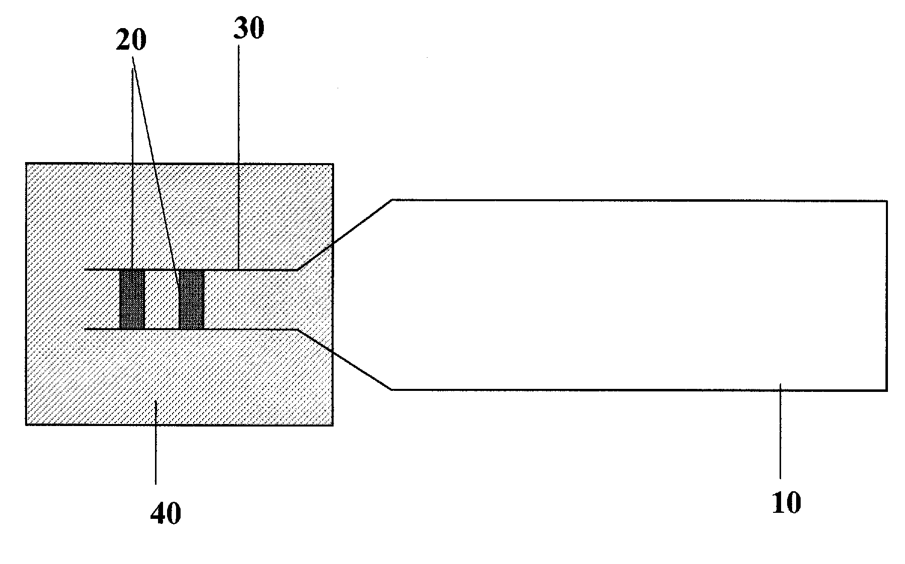
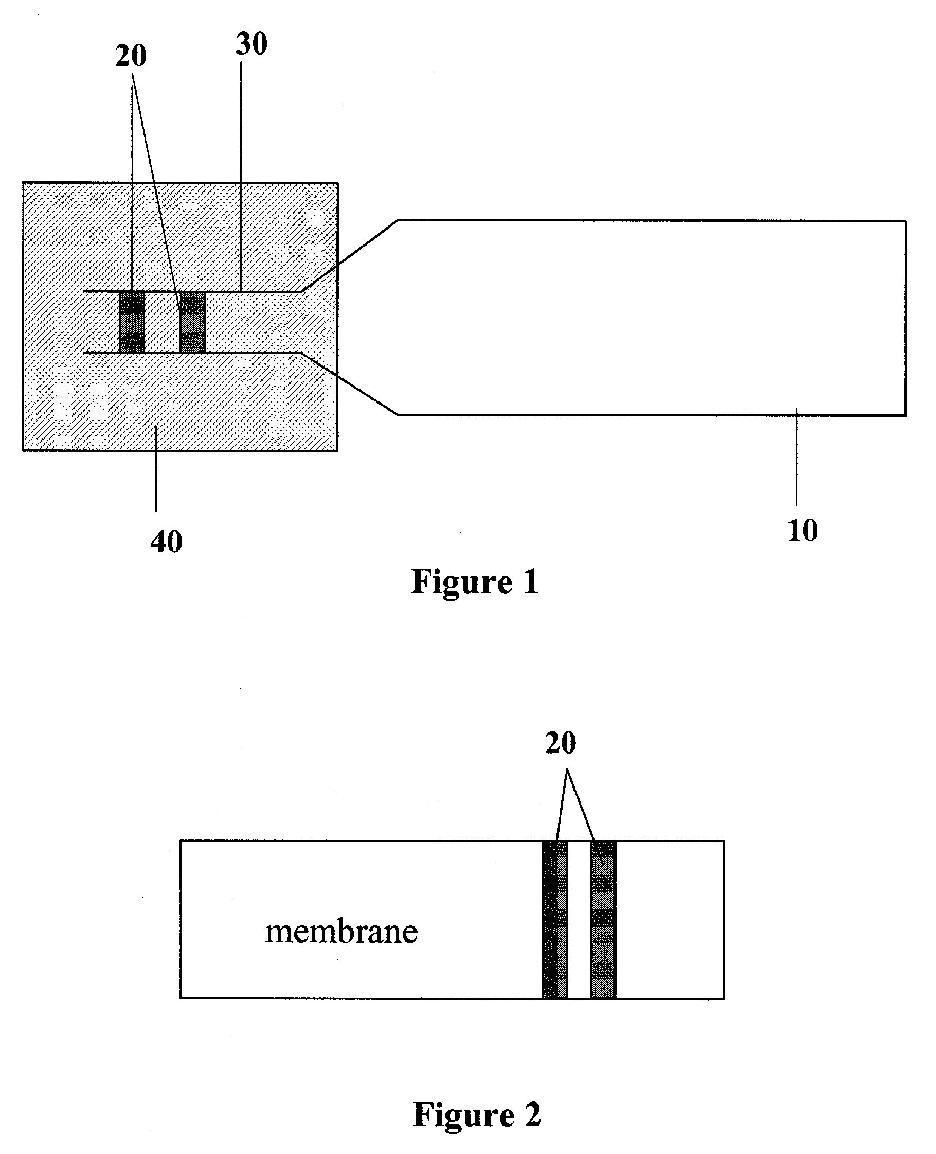
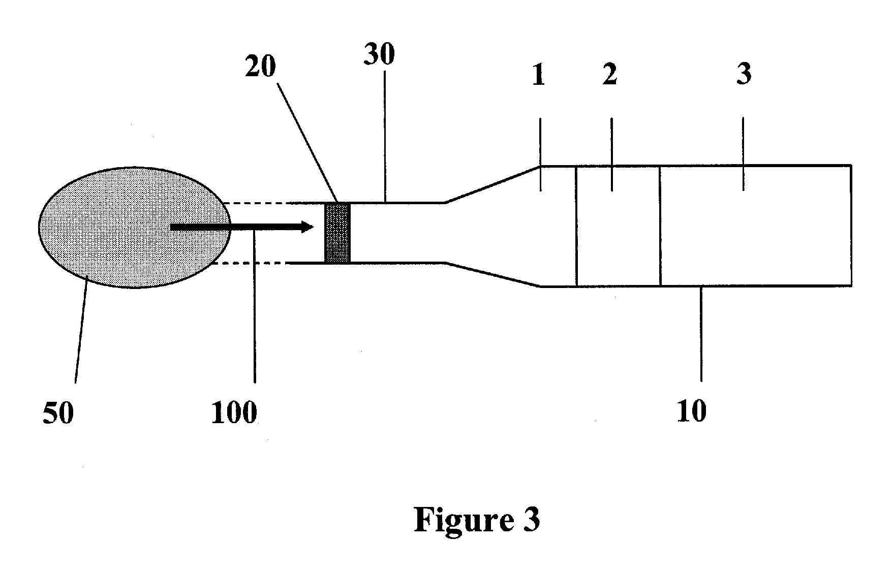
[0049]Other objects and aspects of the invention will become apparent from the following description of the embodiments with reference to the accompanying drawings, which is set forth hereinafter. The embodiments of the present invention can be modified variously. Thus, the scope of the present invention should be construed not limited to the embodiments to be described herein. The embodiments are provided to better explain the present invention to those of ordinary skill in the art. Further, the elements and areas of the drawings are drawn roughly only, and the scope of the present invention is not limited to the relative sizes, shapes and gaps in the drawings. Same reference numerals have been provided in the figures for same element of the invention even when they appear in different figures.

[0050]The term microstructures, posts and capillary generating structures are interchangeable wherever used in the patent specification

[0051]The present invention provides for microfluidic de...


PUM

PropertyMeasurementUnit
total volumeaaaaaaaaaa
lengthaaaaaaaaaa

Abstract

A capillary system for performing surface assays comprising a capillary pump containing at least two zones having different capillary pressures for obtaining controlled flow rate of liquids. The different pressure zones may be created by various means such as by creating posts in the walls of the capillary pump, by having different sized capillary of the different zones, by changing the wetting properties, by defining friction at the walls of the pump or by combinations of any of the above. The capillary system finds use in various surface assays and can be programmed for defining the volume and rate of liquid flowing through the test sites. A microfluidic chip containing assembly of programmed capillary systems for performing need based specific assays and modifications thereof.

Description

FIELD OF THE INVENTION[0001]The present invention relates to the field of microfluidic technology and provides for a capillary system wherein the flow rate of fluids is controlled by using capillary pressures. The capillary system finds its application in various analyses at microscopic level wherein small amounts of reagents, samples and analytes are used and can be applied to an automatic microanalysis system such as biosensors, biochips and high throughput screening.BACKGROUND OF INVENTION[0002]Microanalysis for detection of analyte molecules is routinely employed in various analytical, bio-analytical and clinical applications. It is desirable that such assays have high specificity, use small volumes of reagents and samples, are performed as rapidly as possible and have high-sensitivity.[0003]Assays are optimized to comprise a specific number of steps of standardized duration, along with various reagents, rinsing liquids, and other solutions of well-defined volumes. Once an assay...

Claims


Application Information

Patent Timeline
Patent Type & Authority Applications(United States)
IPC IPC(8): C12Q1/68C25B15/00
CPCB01L3/50273B01L2300/0636B01L2300/0816B01L2300/0864Y10T436/2575B01L2300/161B01L2400/0406B01L2400/086B01L2300/0887
Inventor DELAMARCHE, EMMANUELSCHMID, HEINZJUNCKER, DAVID
Owner IBM CORP
Why Eureka
Try Eureka