Method of patterning gate electrodes by reducing sidewall angles of a mask layer

a gate electrode and mask layer technology, applied in the field of patterning gate electrodes, can solve the problems of reducing the width of the resistor, reducing the drive current capability, and reducing the etch fidelity, so as to improve the efficiency and enhance the profile of the end portion. , the effect of enhancing the profil

Active Publication Date: 2008-01-03
ADVANCED MICRO DEVICES INC
View PDF5 Cites 7 Cited by
  • Summary
  • Abstract
  • Description
  • Claims
  • Application Information

AI Technical Summary

Benefits of technology

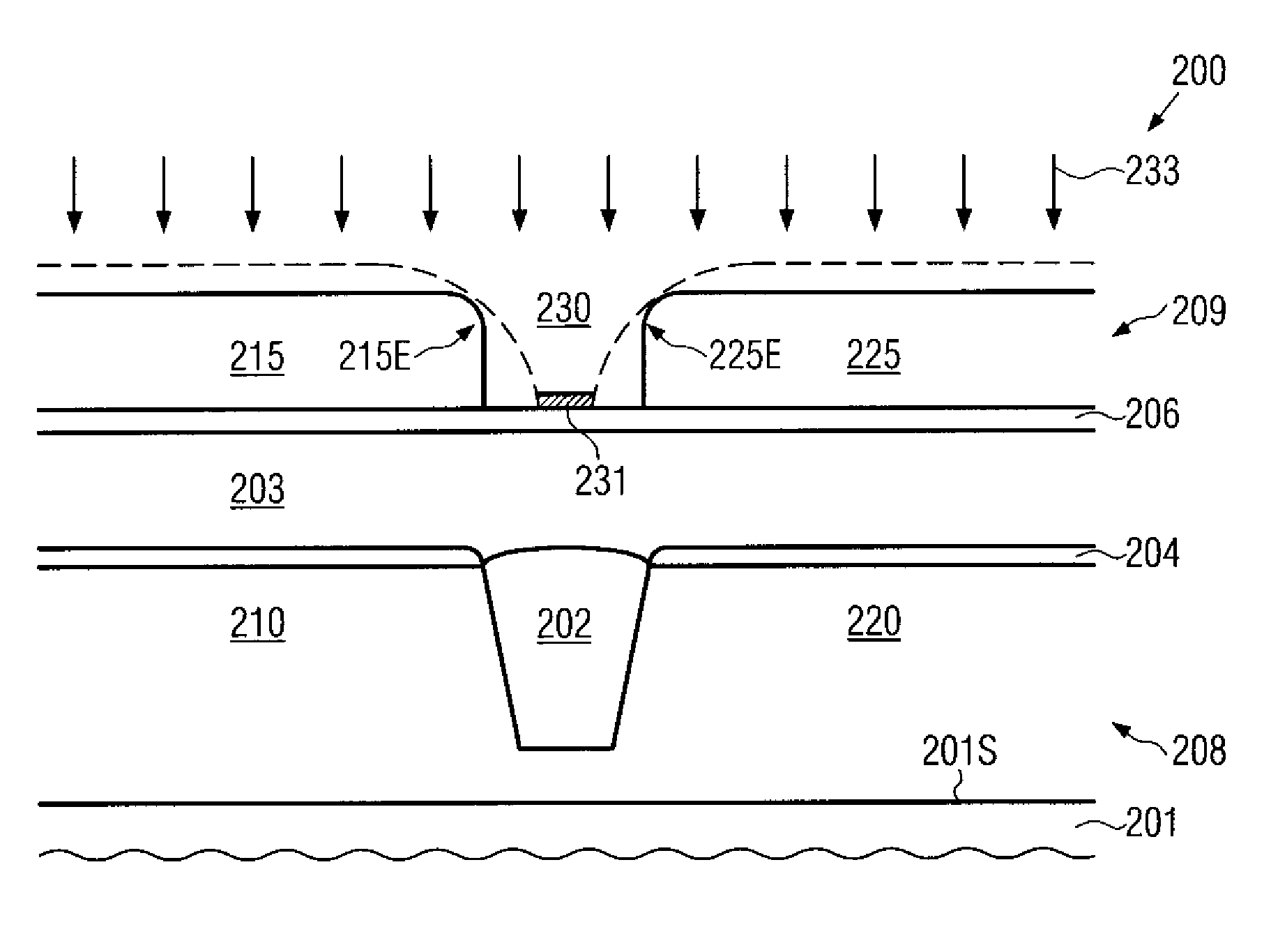
[0015]Generally, the present disclosure is directed to a technique that enables the patterning of semiconductor lines, such as gate electrodes, with increased efficiency by enhancing the profile of an end portion of a mask feature that is formed above an isolation structure. Based on the enhanced profile of the mask feature, respective end portions of the semiconductor line, for instance of the gate electrode, may be patterned with enhanced fidelity, thereby providing the potential for further device scaling without reducing transistor performance due to misaligned gate electrodes or short circuits between opposing end caps of gate electrodes. The enhancement of the profile of respective end portions of a mask feature may be accomplished by significantly reducing the tapering of the respective mask features, as is typically encountered in the conventional resist trim processing, so that a reduced spacing between respective end portions may be used as target values substantially without increasing the probability for creating respective short circuits.

Problems solved by technology

Upon reducing the transistor dimension, the transistor width is also typically reduced in view of packing density and switching speed, which may, however, reduce the drive current capability.
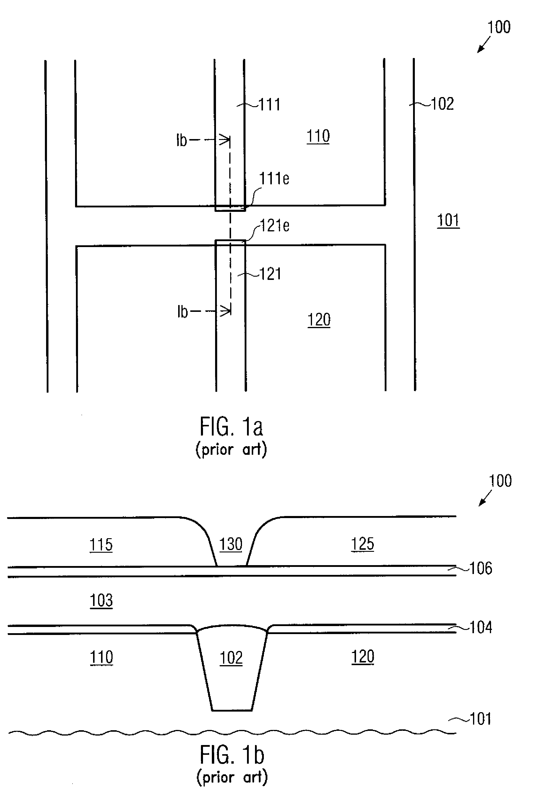
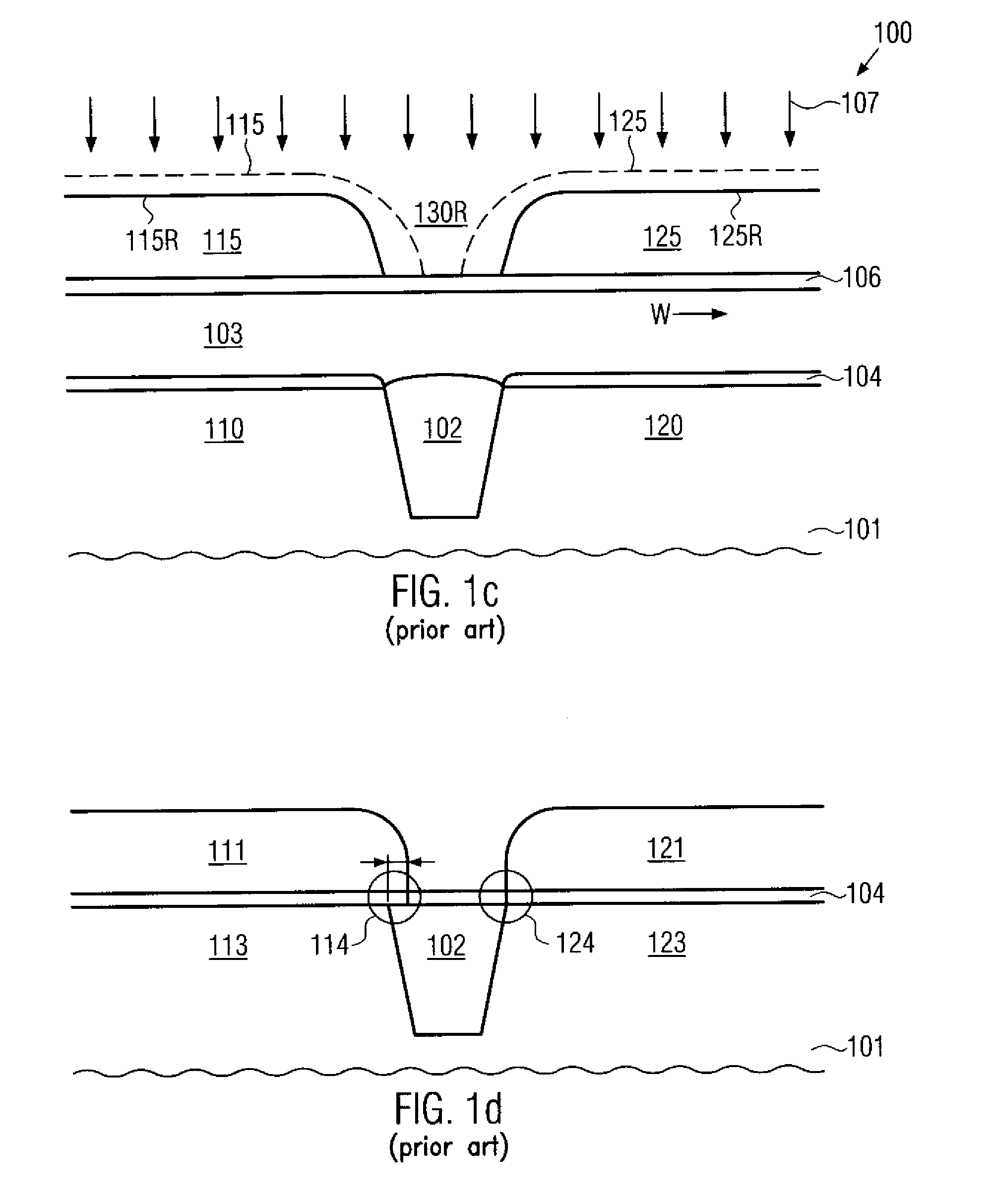
Depending on the characteristics of the respective etch process, a further reduction in size of the resist features 115R, 125R may result and may therefore also reduce the etch fidelity, which may possibly result in reduced overlap of the respective gate electrodes and the trench isolation 102, which may be undesirable with respect to transistor performance.
Consequently, reduced transistor performance may result from a non-overlapping gate electrode.

Method used


Image

  • Method of patterning gate electrodes by reducing sidewall angles of a mask layer
  • Method of patterning gate electrodes by reducing sidewall angles of a mask layer
  • Method of patterning gate electrodes by reducing sidewall angles of a mask layer

Examples


Embodiment Construction

[0027]Various illustrative embodiments of the invention are described below. In the interest of clarity, not all features of an actual implementation are described in this specification. It will of course be appreciated that in the development of any such actual embodiment, numerous implementation-specific decisions must be made to achieve the developers' specific goals, such as compliance with system-related and business-related constraints, which will vary from one implementation to another. Moreover, it will be appreciated that such a development effort might be complex and time-consuming, but would nevertheless be a routine undertaking for those of ordinary skill in the art having the benefit of this disclosure.

[0028]The present subject matter will now be described with reference to the attached figures. Various structures, systems and devices are schematically depicted in the drawings for purposes of explanation only and so as to not obscure the present disclosure with details ...


PUM

PropertyMeasurementUnit
lengthaaaaaaaaaa
lengthaaaaaaaaaa
widthaaaaaaaaaa

Abstract

By performing an anisotropic resist modification prior to the actual resist trimming process, the profile of the end portions of the resist features may be significantly enhanced, for instance by providing substantially vertical sidewall portions. Consequently, an overlap of gate electrodes with the respective isolation structures may be obtained, while nevertheless the probability for a short circuit between opposing end portions of the gate electrodes may be significantly reduced, thereby providing the potential for further scaling down device dimensions.

Description

BACKGROUND OF THE INVENTION[0001]1. Field of the Invention[0002]Generally, the present disclosure relates to the field of fabrication of integrated circuits, and, more particularly, to the patterning of lines, such as gate electrodes, of field effect transistor devices on the basis of a mask layer, such as a resist mask.[0003]2. Description of the Related Art[0004]In modern ultra-high density integrated circuits, device features are steadily decreased to enhance device performance and functionality. One important circuit element in complex integrated circuits is a field effect transistor, which represents a component having a channel region, whose conductivity may be controlled by an electric field that is generated by apply-ing a control voltage to a gate electrode formed near the channel region and separated therefrom by a gate insulation layer. The channel region is generally defined by respective PN junctions formed by an interface of highly doped drain and source regions and an...

Claims


Application Information

Patent Timeline
Patent Type & Authority Applications(United States)
IPC IPC(8): H01L21/302
CPCH01L29/78H01L21/28123
Inventor STEJSKAL, ROLANDKRUEGEL, STEPHANLENSKI, MARKUS
Owner ADVANCED MICRO DEVICES INC
Why Eureka
Try Eureka