Atherectomy devices and methods

a technology of atherectomy and lumen, which is applied in the field of occluded body lumen treatment, can solve the problems of unacceptably high restonosis rate, barotrauma to the vessel, and the embolization of a downstream vessel, and achieve the effect of improving the safety of the devi

Active Publication Date: 2008-01-03
ATHEROMED
View PDF99 Cites 253 Cited by
  • Summary
  • Abstract
  • Description
  • Claims
  • Application Information

AI Technical Summary

Benefits of technology

[0016]The deflecting member can also include a pre-shaped mandrel, or tube where such features are slidable within or relative to the device to produce movement of the cutting head relative to an axis of the device. The devices described herein may have any number of features that allow for locking the device after it is articulated. This feature provides a consistent diameter when sweeping or navigating through the anatomy.
[0017]As discussed herein, some variations of the devices have the ability to articulate. This articulation allows for steering the device to the target site as well as creating a sweeping motion of tissue removal. Accordingly, sheath used in the device can be rotatable about the catheter body, or about an axis of the catheter.
[0018]The devices described herein may have a cutter assembly having a portion of its housing having a curved surface and where the opening forms a plane across the curved surface such that as the cutting surface rotates across the opening, a portion of the cutting surface extends out of the housing through the opening. The cutter assembly may also have various other features as described below that improve the safety of the device as it is articulated while cutting. Furthermore the cutter may have a number of features to impel or drive cut tissue into the cutter assembly for eventual removal by one or more conveying members.

Problems solved by technology

Often plaque is friable and may dislodge naturally or during an endovascular procedure, leading to embolization of a downstream vessel.
Balloon angioplasty is known to cause barotrauma to the vessel from the high pressures required to compress the plaque.
This trauma leads to an unacceptably high rate of restenosis.
Furthermore, this procedure may not be efficient for treatment of elastic-type plaque tissue, where such tissue can spring back to occlude the lumen.
On their own, stents fail to perform well in the peripheral vasculature for a variety of reasons.
A stent with the necessary structural integrity to supply sufficient radial force to reopen the artery often does not perform well in the harsh mechanical environment of the peripheral vasculature.
Such an environment may lead to stent failure (strut cracking, stent crushing, etc.) that eventually compromises the ability of the stent to maintain lumen diameter over the long-term.
On the other hand, a stent that is able to withstand the harsh mechanical aspects of the periphery often will not supply enough radial force to open the vessel satisfactorily.

Method used


Image

  • Atherectomy devices and methods
  • Atherectomy devices and methods
  • Atherectomy devices and methods

Examples


Embodiment Construction

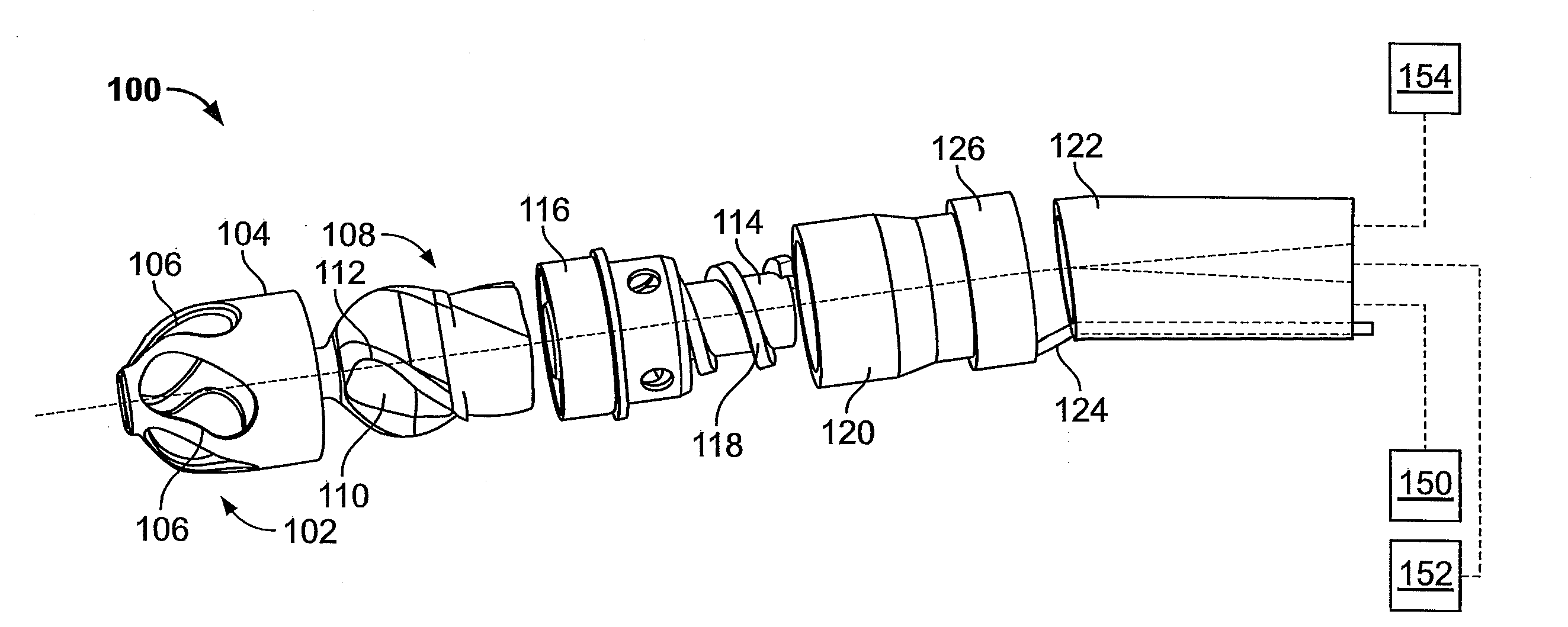
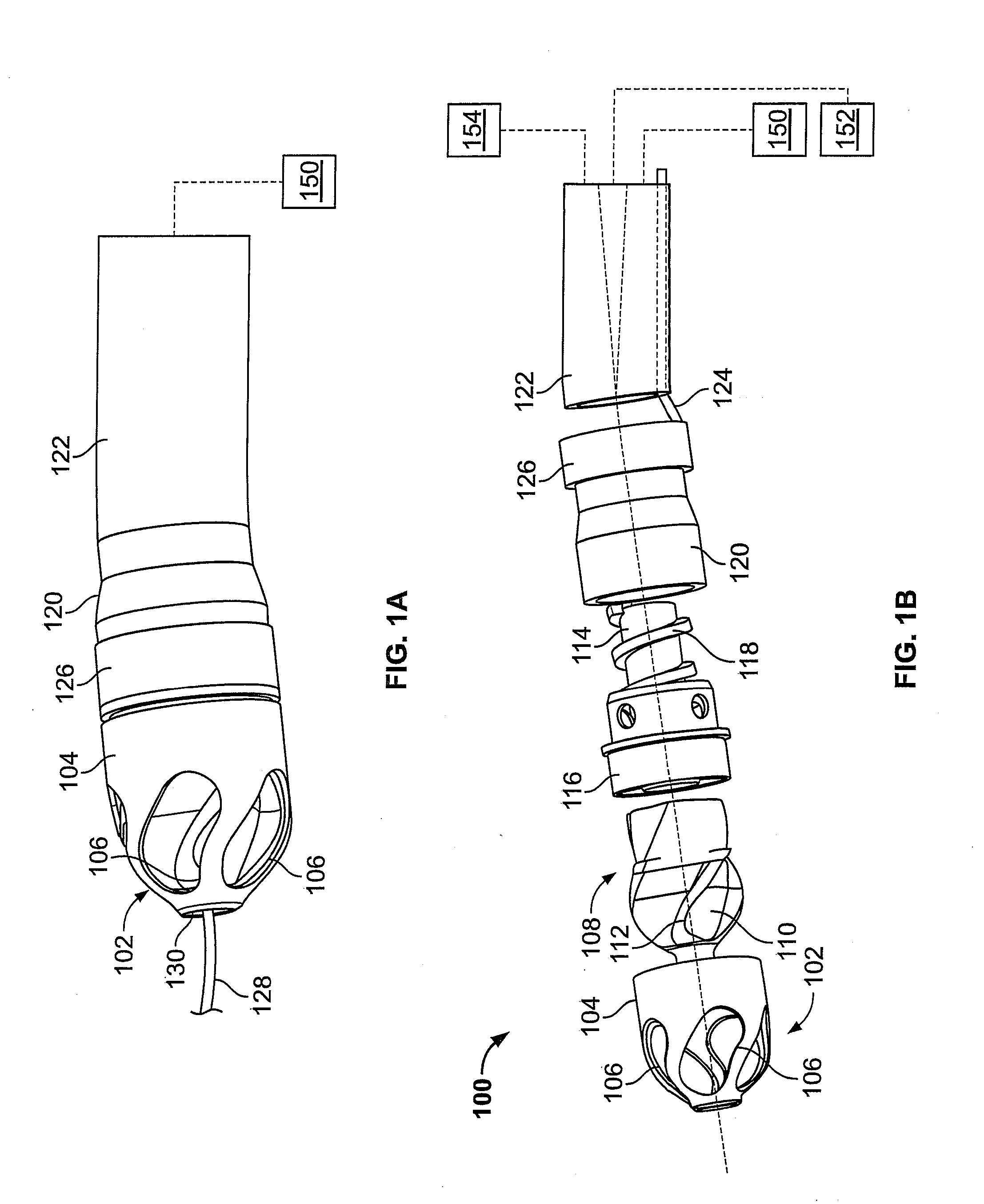
[0051]FIG. 1A illustrates an exemplary variation of a device 100 according to the present invention. As shown the device 100 includes a cutter assembly 102 affixed to a catheter body 120. As shown, the catheter body may be optionally located within an outer sheath 122.

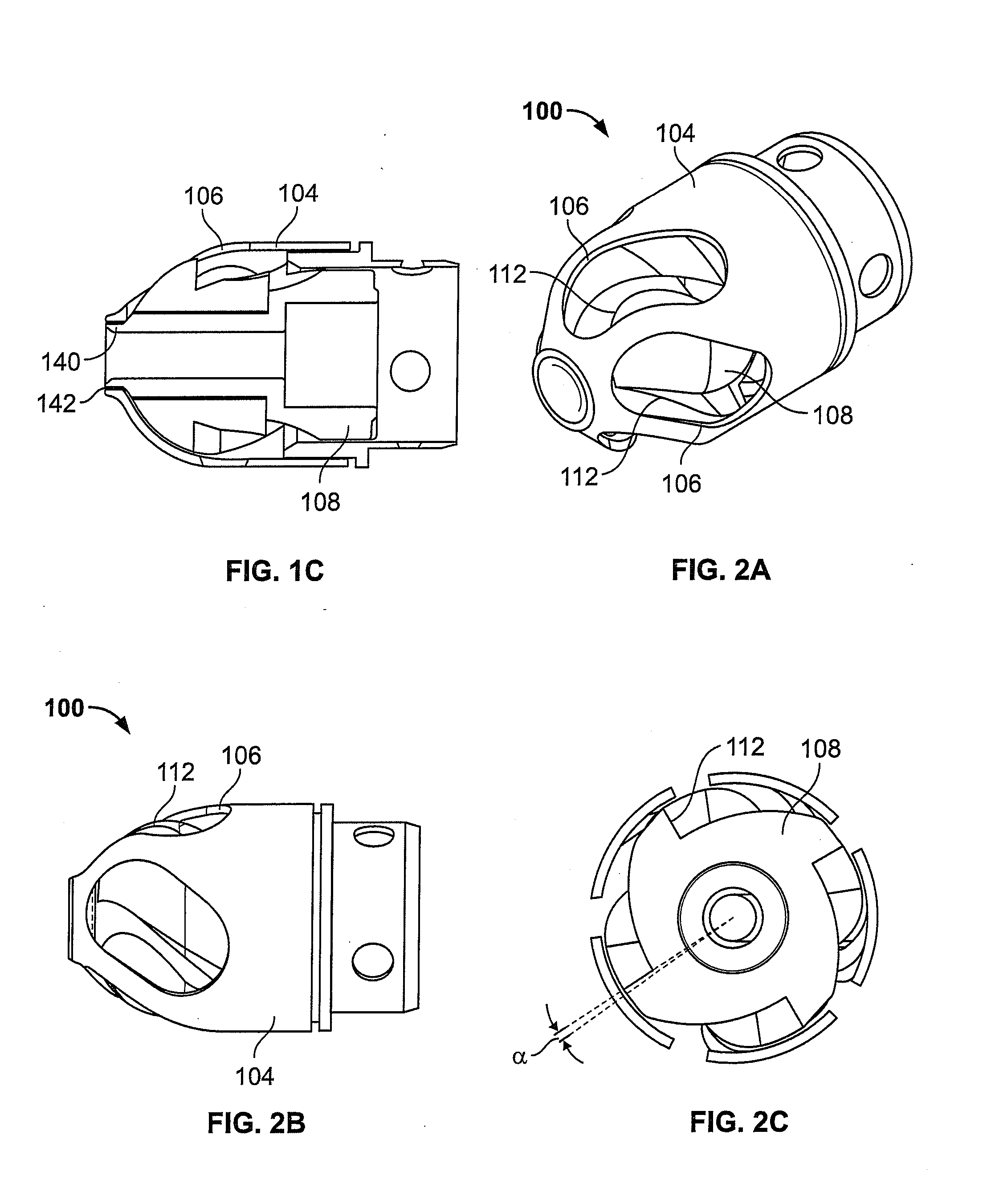
[0052]FIG. 1B illustrates an exploded view of the device 100 of FIG. 1A. As shown, the cutter assembly 102 includes a housing 104 with a plurality of openings 106. A cutter 108 is located within the housing 104. The cutter 108 includes one or more flutes 110 each of which includes an edge or cutting surface 112. The cutter is coupled to a rotating mechanism 150. In this variation the rotating mechanism couples to the cutter via a torque shaft 114 that transmits rotational energy from the rotating mechanism 150 (e.g., an electric, pneumatic, fluid, gas, or other motor) to the cutter 108. Variations of the devices include use of a rotating mechanism 150 located entirely within the body of the device 100. In one variation...


PUM


Abstract

The devices and methods generally relate to treatment of occluded body lumens. In particular, the present devices and method relate to removal of the occluding material from the blood vessels as well as other body lumens.

Description

CROSS-REFERENCE[0001]This filing is a non-provisional of U.S. Provisional Application Ser. No. 60 / 806,417 entitled “Atherectomy Device” filed Jun. 30, 2006 and is a non-provisional of U.S. Provisional Application Ser. No. 60 / 820,475 entitled “Atherectomy Device” filed Jul. 26, 2006, the entirety of each of which are hereby incorporated reference.BACKGROUND OF THE INVENTION[0002]1. Field of the Invention[0003]The devices and methods described below generally relate to treatment of occluded body lumens. In particular, the present devices and method relate to removal of the occluding material from the blood vessels as well as other body lumens.[0004]2. Description of the Background Art[0005]Atherosclerosis is a progressive disease. In this disease, lesions of the arteries are formed by accumulation of plaque and neointimal hyperplasia causing an obstruction of blood flow. Often plaque is friable and may dislodge naturally or during an endovascular procedure, leading to embolization of ...

Claims


Application Information

Patent Timeline
Patent Type & Authority Applications(United States)
IPC IPC(8): A61B17/3207
CPCA61B17/32075A61B17/320758A61B17/320783A61B2017/003A61B2017/00539A61B2017/00685A61F2/86A61B2017/22068A61B2017/22071A61B2017/22094A61B2017/320032A61B2017/320775A61B2019/481A61B2017/22039A61B2090/08021
Inventor TO, JOHNDANEK, CHRISTOPHER JAMES
Owner ATHEROMED
Why Eureka
Try Eureka