Method for manufacturing lenses, in particular for an imager comprising a diaphragm

Active Publication Date: 2008-01-10
STMICROELECTRONICS SRL
View PDF8 Cites 101 Cited by
  • Summary
  • Abstract
  • Description
  • Claims
  • Application Information

AI Technical Summary

Benefits of technology

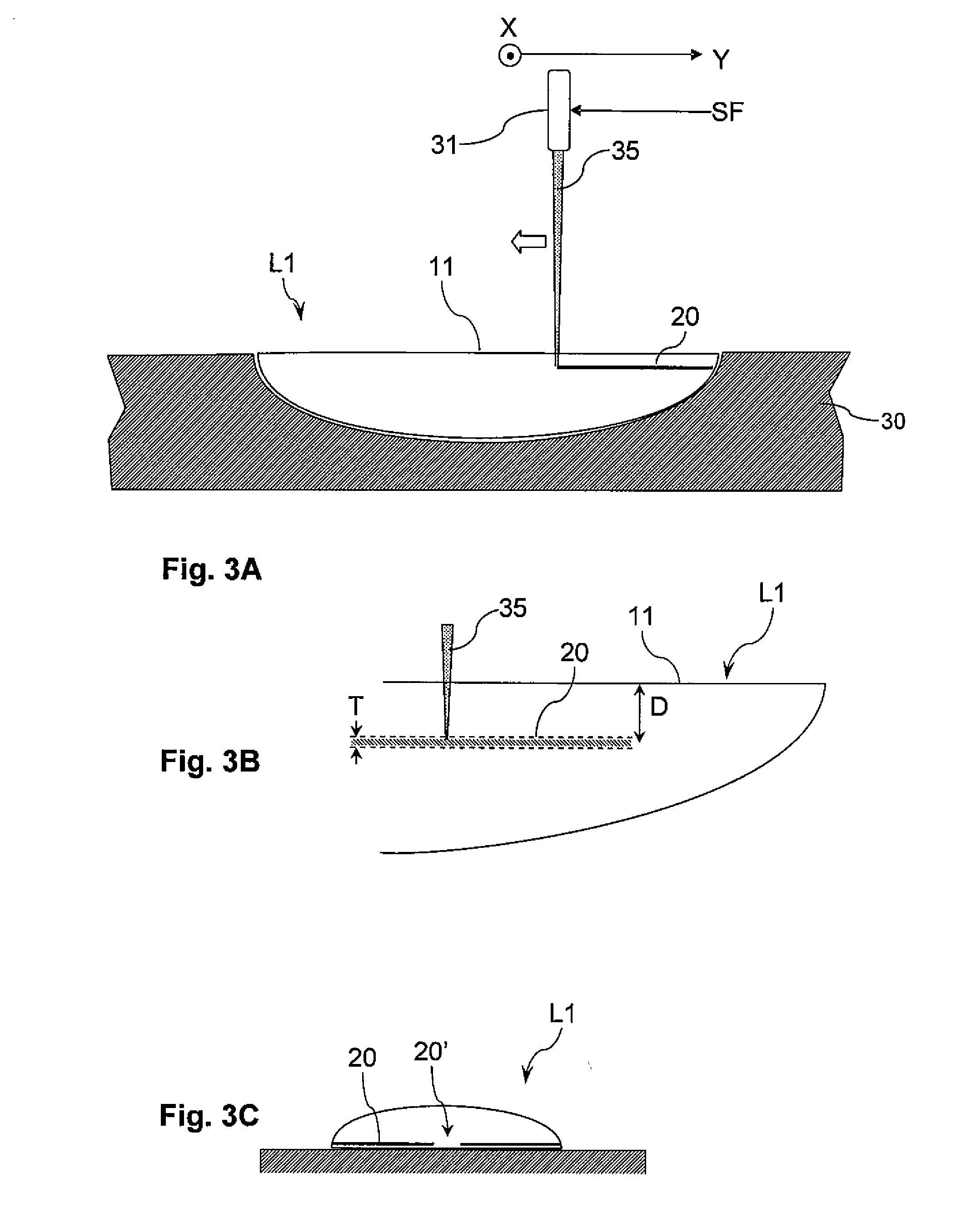
[0014] According to one embodiment, the laser beam is applied to the lens by using a variable focus device compris

Problems solved by technology

Such CMOS imagers were initially used to produce low resolution image sensors of mediocre quality (for example web cameras).
Such a micro-module for c

Method used


Image

  • Method for manufacturing lenses, in particular for an imager comprising a diaphragm
  • Method for manufacturing lenses, in particular for an imager comprising a diaphragm
  • Method for manufacturing lenses, in particular for an imager comprising a diaphragm

Examples


Embodiment Construction

[0045] In the following description, numerous specific details are given to provide a thorough understanding of embodiments. One skilled in the relevant art will recognize, however, that the invention can be practiced without one or more of the specific details, or with other methods, components, materials, etc. In other instances, well-known structures, materials, or operations are not shown or described in detail to avoid obscuring aspects of the invention.

[0046] Reference throughout this specification to “one embodiment” or “an embodiment” means that a particular feature, structure, or characteristic described in connection with the embodiment is included in at least one embodiment. Thus, the appearances of the phrases “in one embodiment” or “in an embodiment” in various places throughout this specification are not necessarily all referring to the same embodiment. Furthermore, the particular features, structures, or characteristics may be combined in any suitable manner in one o...


PUM

PropertyMeasurementUnit
Distanceaaaaaaaaaa
Molecular structureaaaaaaaaaa
Optical propertiesaaaaaaaaaa

Abstract

A method for manufacturing a lens of a polymer material, comprises producing in the core of the lens or on the surface of the latter at least one opaque zone having an optical function, by locally degrading the molecular structure of the polymer material using a beam of laser light. Example application is provided in particular but not exclusively to CMOS imagers.

Description

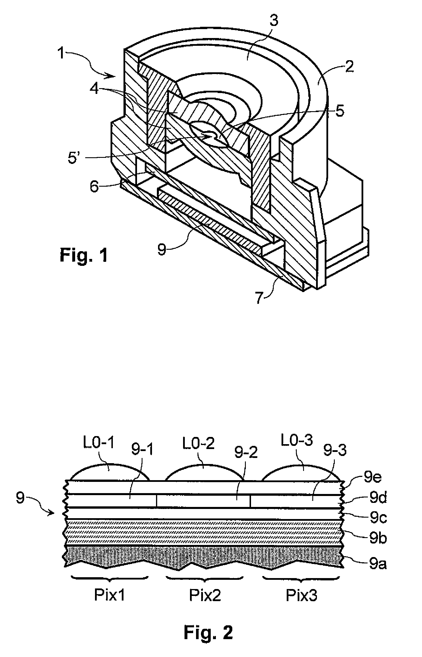
TECHNICAL FIELD [0001] The present disclosure generally relates to the manufacturing of optical lenses for integrated imagers and in particular but not exclusively for CMOS imagers. BACKGROUND INFORMATION [0002] Imagers produced according to the CMOS (“Complementary Metal Oxide Semiconductor”) technology are currently the subject of an increasing number of applications due to their low cost price in comparison with CCD (Charge Coupled Device) imagers. Such CMOS imagers were initially used to produce low resolution image sensors of mediocre quality (for example web cameras). Today, after major investment in research and development, CMOS imagers can compete with CCD imagers. [0003]FIG. 1 represents an example of a micro-module 1 for capturing images using a CMOS imager, intended for example to be mounted into a portable device such as a mobile telephone, a camera or a video camera. The micro-module 1 comprises a frame 2, a lens-holder block 3, one or more lenses 4 and a diaphragm 5 a...

Claims


Application Information

Patent Timeline
IPC IPC(8): H01L31/113B29D11/00G02B3/00G02B5/18
CPCB29C71/04B29C2791/009B29D11/00009B29L2011/0016G02B3/0068G02B3/0018G02B3/0025G02B3/0056B41M5/265
Inventor MIONETTO, ROBERTO
Owner STMICROELECTRONICS SRL
Why Eureka
Try Eureka