Switch detection device using RFID tag

a detection device and rfid technology, applied in the direction of wing accessories, mechanical actuation of burglar alarms, instruments, etc., can solve the problems of not being able to track the product, the rfid reader is not able to read any information from the rfid tag, and the error is frequently found

Inactive Publication Date: 2008-01-10
CHUNG HUA UNIVERSITY
View PDF10 Cites 33 Cited by
  • Summary
  • Abstract
  • Description
  • Claims
  • Application Information

AI Technical Summary

Benefits of technology

[0012]A further object of the present invention, therefore, is to provide a switch operation detection using RFID tags. The switch operation detection comprises a switch which is driven to turn on either by mechanical force or magnetic induction. This connection or disconnection of the switch respective

Problems solved by technology

However, in operation, errors are frequently found, especially when the barcode reader is not closed enough to the barcode for detection.
However, it is noted that once the RFID tag is destroyed, whether it is destroyed intentionally by the consumer or unintentionally by the manufacturing machine or workers,

Method used


Image

  • Switch detection device using RFID tag
  • Switch detection device using RFID tag
  • Switch detection device using RFID tag

Examples


first embodiment

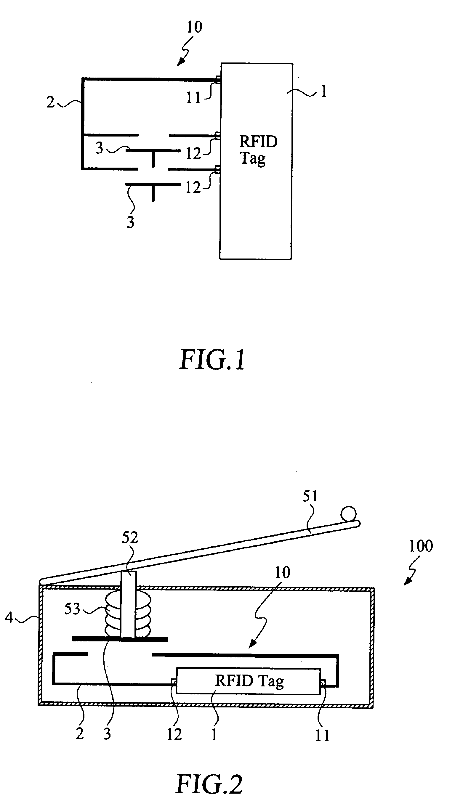
[0034]With reference to the drawings and in particular to FIGS. 1 and 2, FIG. 1 is a detection circuit of a switch detection device with a RFID tag in accordance with the present invention, and FIG. 2 is a schematic view of a switch detection device in accordance with the present invention. The detection circuit of the switch detection device is generally designated with reference numeral 10, which comprises a RFID tag 1. The RFID tag 1 includes a reference voltage port 11 and a plurality of data input / output ports 12. The reference voltage port 11 is connected to a first end of a conducting circuit loop 2. The conducting circuit loop 2 is provided with, for example two second ends which are connected to the data input / output ports 12 respectively through a switch 3 capable of controlling the opening or closing of the conducting circuit loop 2.

[0035]In practice, the data input / output ports 12 may be designed in either a pull high or a pull low voltage port. If the data input / output ...

sixth embodiment

[0052]FIG. 7 shows the switch detection device of the present invention. The switch detection device is incorporated to a lever lock assembly 71 which includes a rotatable door handle 711, a central handle axis 712 and a movable lock pin 713. The door handle 711 is manually rotatable around the central handle axis 712. When the door handle 711 is turned by the user, the door handle 711 rotates along a rotation direction I. The rotation of the door handle 711 drives the lock pin 713 to move along a direction II to engage to or disengage from a hole 81 formed at a corresponding position at a door frame 8.

[0053]The lever lock assembly 71 incorporates a detection circuit 10 of FIG. 1. The detection circuit 10 is positioned at the displacement pathway of the lock pin 713. When the lock pin 713 moves along the direction II, the lock pin 713 drives the switch 3 of the detection circuit 10 to turn on or off and the RFID tag 1 generates a signal to a nearby RFID reader to indicate the lockin...

ninth embodiment

[0058]FIG. 10 shows the switch detection device of the present invention. The switch detection device is incorporated to a water flow meter or a gas flow meter. The water flow meter 73 generally comprises a recording mechanism that includes a number of parallel odometer wheels 731 arranged along a central axle 732. Each of the odometer wheels 731 has gradations around the perimeter to indicate water usage. A detection circuit 10 is mounted at the axle 732 for detecting the degrees of rotation of each of the odometer wheels 731. The rotation of the odometer wheel 731 indicates the measured value of the corresponding odometer wheel 731. From the rotations of the odometer wheels 731, the water usage is measured. A signal representing the measured data is transmitted by the RFID tag to a nearby RFID reader.

[0059]FIGS. 11 to 13 show various applications of a tenth embodiment of the switch detection device of the present invention. In the tenth embodiment, the switch detection device is i...


PUM


Abstract

A switch detection device using RFID tags is disclosed. The switch detection device includes a RFID tag, a conducting circuit loop and a switch connected to the conducting circuit loop to form a control circuit. The switch is controlled to turn on or off, leading to the closing or opening of the control circuit. The RFID tag detects the state of the conducting circuit loop and transmits a signal representing the opened/closed state to a RFID reader. The switch detection device is incorporated to a turning operation mechanism which includes a lever lock assembly, a deadbolt lock assembly, a window sash lock assembly, an odometer wheel, a hinge provided with a first hinge member and a second hinge member interconnected by a central axle, a door closer, a water faucet, a rotatable switch, or a rotatable lock.

Description

FIELD OF THE INVENTION[0001]The present invention relates to a switch detection device, and in particular to a switch detection device using Radio Frequency Identification (RFID) tag. The switch detection device using RFID tag transmits the product information stored in the RFID tag and can be used to control or monitor the ON / OFF of a switch like a water faucet.BACKGROUND OF THE INVENTION[0002]Barcode reader is widely used in the industry for reading a message on a barcode adhered on an object. However, in operation, errors are frequently found, especially when the barcode reader is not closed enough to the barcode for detection. Moreover, it is required to project light on the barcode for the barcode reader to read.[0003]Recently, it is found that radio frequency identification (RFID) techniques have been applied to many applications for easily obtaining messages on an object. The message is stored in a RFID tag and a signal is transmitted wirelessly from the RFID tag to a RFID re...

Claims


Application Information

Patent Timeline
IPC IPC(8): G08B13/14G08B21/00
CPCE05B2047/0069E05C3/043E05Y2900/132E05Y2400/326E05Y2900/148E05D11/00
Inventor HWANG, CHI-KUANGWANG, CHIH-HUTIEN, CHING-CHENGCHUNG, IN-HANGLEE, BORE-KUENCHEN, TUNG-CHOUWU, CHIA-WENCHIU, CHIEN-JUNGYEN, MING-CHINGCHEN, JWU-E
Owner CHUNG HUA UNIVERSITY
Why Eureka
Try Eureka