
Protective circuit module for secondary battery and battery pack using the same

Active Publication Date: 2008-01-10
SAMSUNG SDI CO LTD
View PDF7 Cites 49 Cited by
  • Summary
  • Abstract
  • Description
  • Claims
  • Application Information

AI Technical Summary

Benefits of technology

[0012]A protective circuit module for a secondary battery includes: a circuit board; at least one protection control circuit element on the circuit board for preventing overcharge and over-discharge of the secondary battery; a first conductive pad coupled to the circuit board; and a positive temperature coefficient device between the at least one protection control circuit element and the first conductive pad such that when a secondary battery temperature reaches a threshold value, resistance of the positive temperature coefficient device is increased and battery current is reduced.
[0023]In accordance with another exemplary embodiment, a battery pack is provided including a secondary battery. A first electrode tab and a second electrode tab protrude from the secondary battery. A protective circuit is provided including: a circuit board; at least one protection control circuit element for preventing overcharge and over-discharge of the secondary battery; a first conductive pad coupled to the circuit board; and a positive temperature coefficient device between the at least one protection control circuit element and the first conductive pad such that when a secondary battery temperature reaches a threshold value, resistance of the positive temperature coefficient device is increased and battery current is reduced. A resin secures the protective circuit module to the secondary battery while exposing the electrode terminals of the circuit board.
[0027]Also, according to the present invention, since the PTC device is connected to the protective circuit module by the serial resistance welding or direct resistance welding method, a high temperature is not applied to the PTC material so that it is possible to prevent the characteristics of the PTC device from deteriorating.
[0029]Also, according to the present invention, the resin molding is performed in a state where the protective circuit module is erected in front of the secondary battery so that it is possible to reduce the size of the battery pack and to increase the capacity of the battery pack of the same size.
[0030]Also, according to the present invention, the protrusions of a predetermined thickness are further formed on each of the top and bottom of the protective circuit module so that it is possible to correctly position the electrode terminals formed in the protective circuit module in the right center, to prevent the resin from being formed to the undesired positions of the electrode terminals, and to thus prevent the defects in the external appearance from being generated.

Problems solved by technology

In a conventional secondary battery, because the PTC device and protective circuit module are mounted in the secondary battery during the pack assembly process, the mountability and configurability of the PTC device and protective circuit module deteriorate.
Therefore, when the temperature of the secondary battery increases, a delay may occur before the PTC material is activated.
Therefore, it is difficult to accurately position electrode terminals in the protective circuit module, resulting in the resin being formed in undesired positions with respect to the electrode terminals.

Method used


Image

  • Protective circuit module for secondary battery and battery pack using the same
  • Protective circuit module for secondary battery and battery pack using the same
  • Protective circuit module for secondary battery and battery pack using the same

Examples


Embodiment Construction

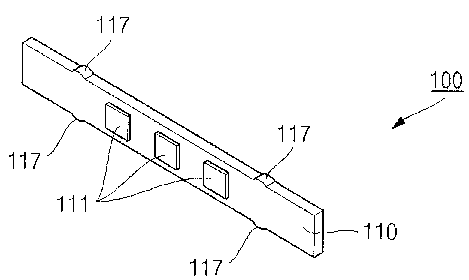
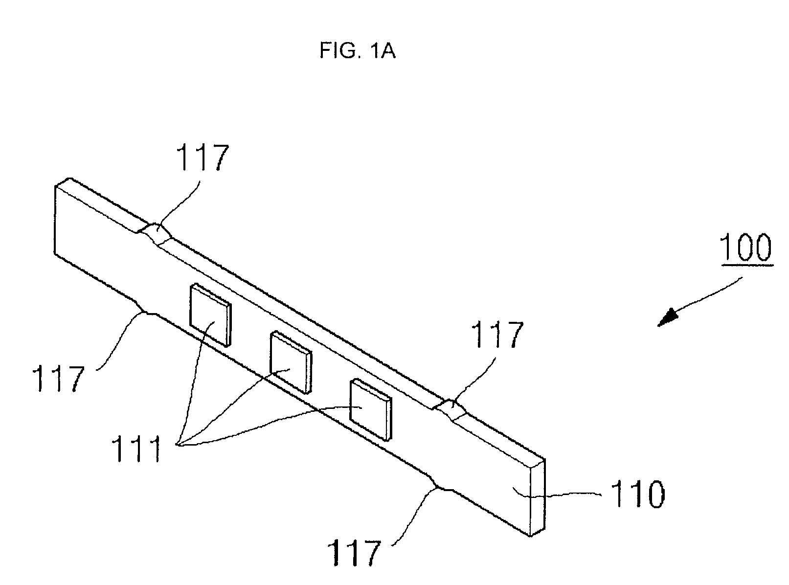
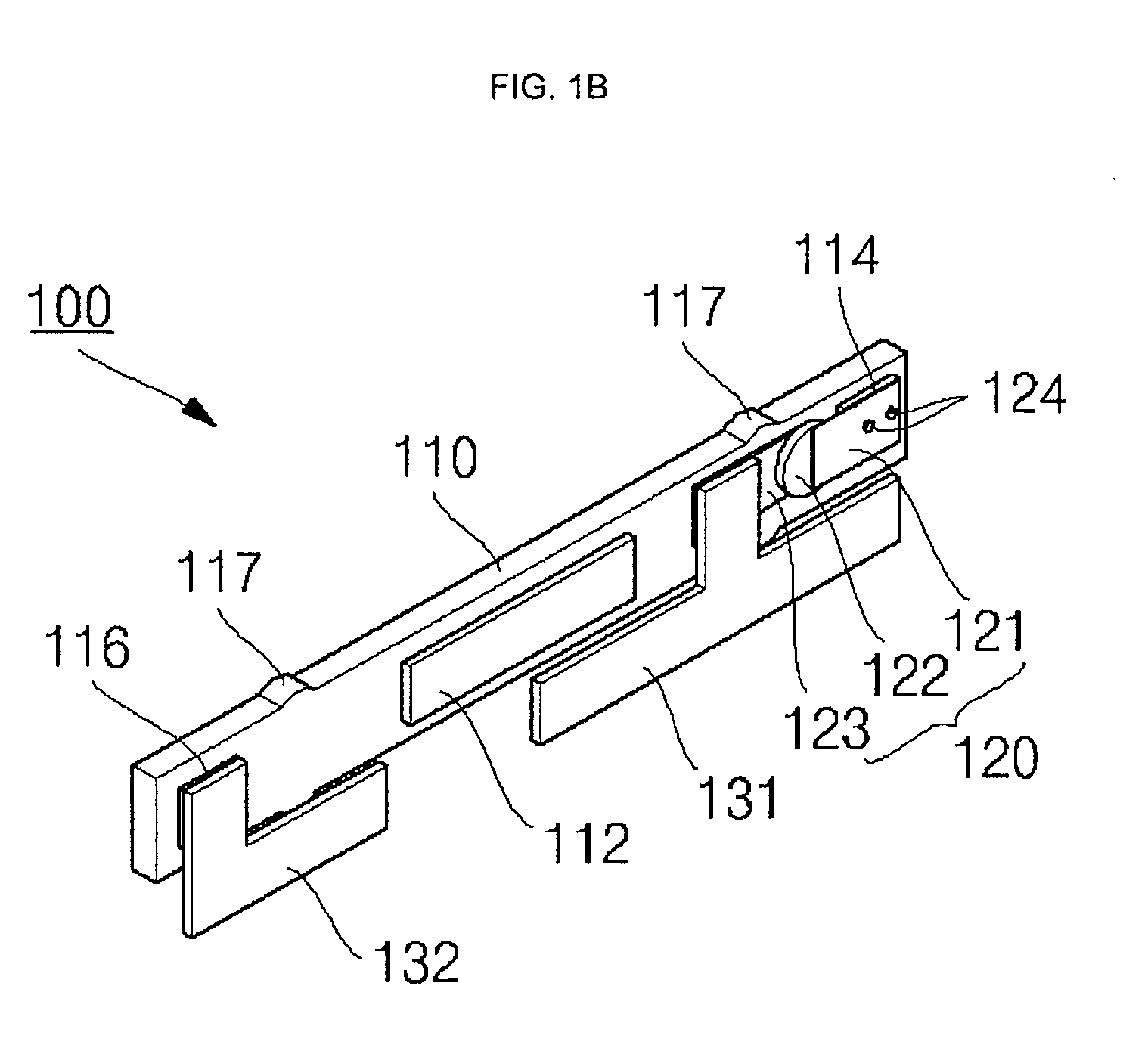
[0042]As illustrated in FIGS. 1A to 1C, an exemplary protective circuit module 100 for a secondary battery includes a circuit board 110, a PTC device 120 connected to the circuit board 110, and conductive leads 131, 132 connected to the circuit board 110 and to the PTC device 120.

[0043]A rigid printed circuit board (RPCB), a flexible printed circuit board (FPCB), or an equivalent can be used as the circuit board 110, but is not limited thereto. Electrode terminals 111 are formed on a planar surface of the circuit board 110 and protection control circuit elements 112 are mounted on a planar surface of the circuit board 110. The electrode terminals 111 may be electrically connected to an external charger or an external system, and the plurality of protection control circuit elements 112 connected to electrode terminals 111 through the circuit board may prevent the overcharge, over-discharge, and over-current of a secondary battery 310 (FIG. 5A). A first conductive pad 114 and a second...


PUM


Abstract

A protective circuit module for a secondary battery. The protective circuit module includes a circuit board. At least one protection control circuit element for preventing overcharge and over-discharge of the secondary battery is mounted on the circuit board. A first conductive pad is coupled to the circuit board. A positive temperature coefficient device is between the at least one protection control circuit and the first conductive pad such that when a secondary battery temperature reaches a threshold value, resistance of the positive temperature coefficient device is increased and battery current is reduced.

Description

CROSS-REFERENCE TO RELATED APPLICATIONS[0001]This application claims priority to and the benefits of Korean Patent Application No. 10-2006-0062458, filed on Jul. 4, 2006, in the Korean Intellectual Property Office, the entire content of which is incorporated herein by reference.BACKGROUND[0002]1. Field of the Invention[0003]The present invention relates to a secondary battery, and more particularly, to a protective circuit module for a secondary battery having improved mountability and configuration.[0004]2. Discussion of Related Art[0005]In general, a secondary battery is a rechargeable battery. High performance secondary batteries are divided into Ni-MH secondary batteries and lithium secondary batteries. Lithium secondary batteries include lithium metal secondary batteries, lithium ion secondary batteries (polygon type, cylinder type, and pouch type), lithium ion polymer secondary batteries, and lithium polymer secondary batteries.[0006]Power demands of small secondary batteries ...

Claims


Application Information

Patent Timeline
IPC IPC(8): H01M10/02H02H7/18
CPCH01M2/1061H01M10/42H01M10/425H02H7/18H01M10/4257H02H5/042H01M2200/106Y02E60/10
Inventor KOH, SEOK
Owner SAMSUNG SDI CO LTD
Learn More