Oil return structure for internal combustion engine

a technology of internal combustion engine and return structure, which is applied in the direction of pressure lubrication, lubrication of auxiliaries, lubrication elements, etc., can solve the disadvantage of increasing total machining costs, sludge build-up in the oil reservoir, and the lower pressure in the oil separator, so as to prevent sludge from building up

Inactive Publication Date: 2008-01-17
TOYOTA JIDOSHA KK
View PDF22 Cites 32 Cited by
  • Summary
  • Abstract
  • Description
  • Claims
  • Application Information

AI Technical Summary

Benefits of technology

[0013]The present invention provides an oil return structure for an internal combustion engine that prevents backflow of blow-by gas, ensures t

Problems solved by technology

This results in lower pressure in the oil separator than in the crank chamber and the cam chamber.
Accordingly, this airflow may cause blow-by gas containing a large amount of vaporized oil to flow into the intake system without t

Method used


Image

  • Oil return structure for internal combustion engine
  • Oil return structure for internal combustion engine
  • Oil return structure for internal combustion engine

Examples


Embodiment Construction

[0035]Example embodiments of the invention will be described below with reference to the accompanying drawings.

[0036]An oil return structure of the invention that is applied to a V-type engine (internal combustion engine) for automobile will be described below.

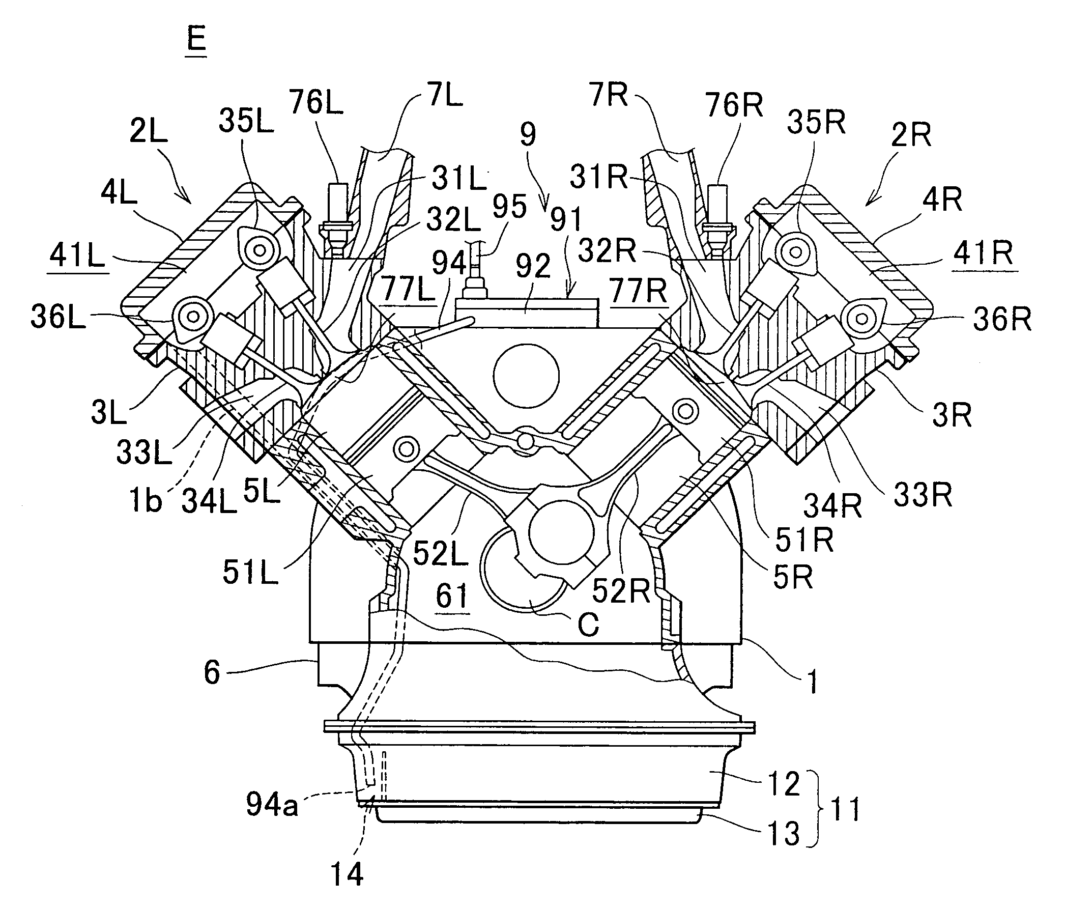
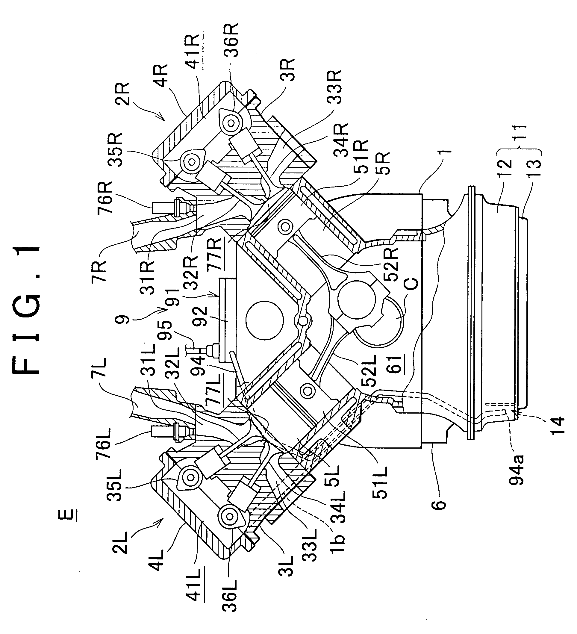
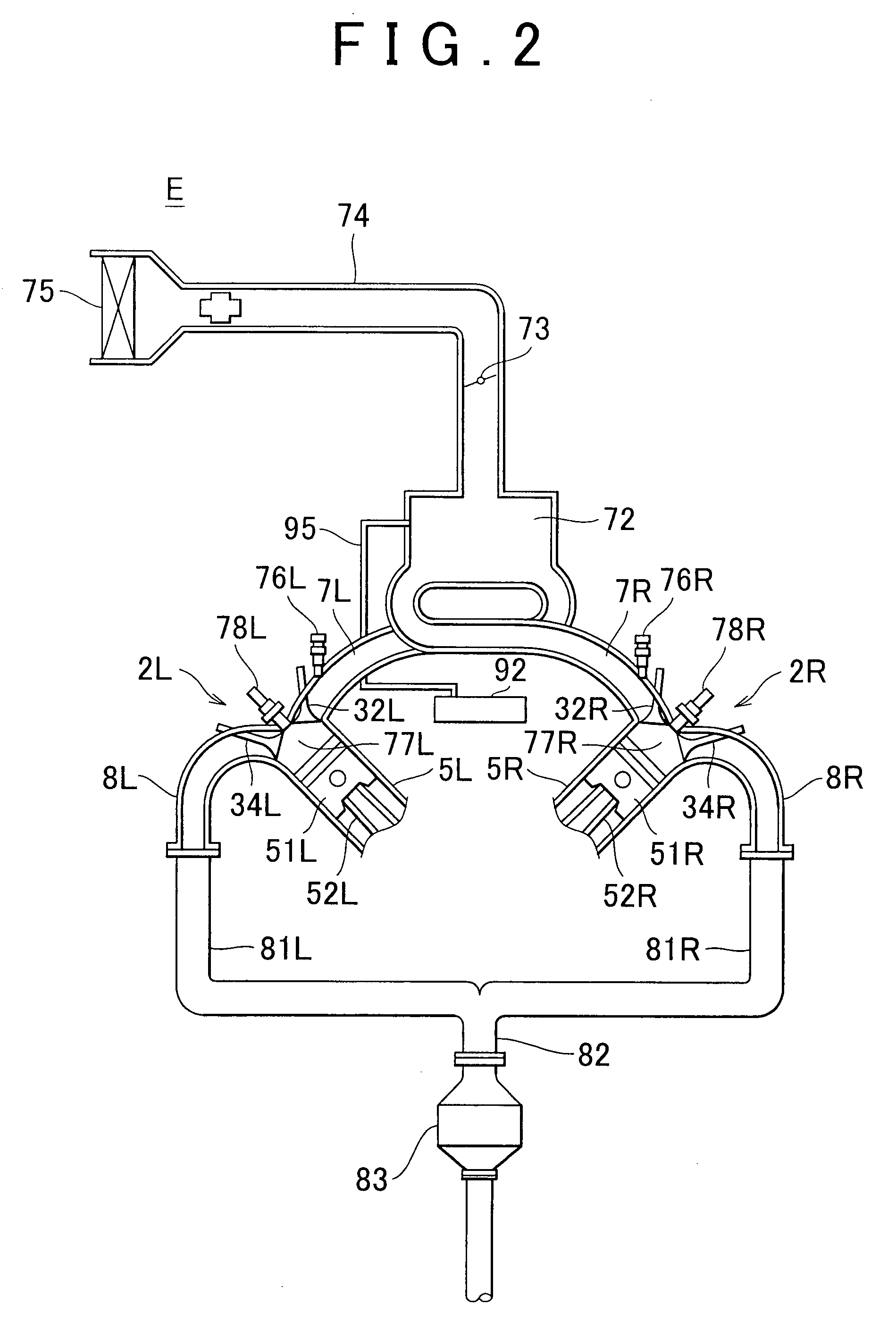
[0037]First, an overall structure of the V-type engine E (hereinafter sometimes referred to as engine) is described with reference to FIGS. 1 to 3. FIG. 1 schematically shows an interior of the V-type engine E, when viewed in the axial direction of a crankshaft C. FIG. 2 is a schematic system structure diagram of the V-type engine E, an intake system, and an exhaust system. FIGS. 3A and 3B show the V-type engine E provided with a PCV system having an oil separator including a separator case, in which the separator case is mounted between banks of the engine E (the outline of the engine E and the form of a crank chamber are shown in the phantom lines). FIG. 3A is a rear view of the engine E. FIG. 3B is a front view of the engin...


PUM


Abstract

An oil pan is provided below a crankcase of an engine. The oil pan has an oil reservoir in its upper case. An oil discharge pipe is located within the oil reservoir, the oil discharge pipe extending from an oil separator of a PCV system. The oil reservoir protrudes inward of an inner wall surface of a lower case. The oil reservoir has an oil drain hole on a bottom surface at its inwardly protruding portion. The oil reservoir communicates with a lower chamber through the oil drain hole.

Description

INCORPORATION BY REFERENCE[0001]The disclosure of Japanese Patent Application No. 2006-190637 filed on Jul. 11, 2006 including the specification, drawings and abstract is incorporated herein by reference in its entirety.BACKGROUND OF THE INVENTION[0002]1. Field of the Invention[0003]The present invention relates to an oil return structure for an internal combustion engine.[0004]2. Description of the Related Art[0005]In a known art, an oil pan is located at the bottom of the crankcase of an internal combustion engine. The oil pan holds oil (lubricating oil) to lubricate and cool moving (sliding) engine parts. Oil held in the oil pan is delivered to the respective engine parts by the oil pump when the engine runs. After lubricating and cooling these engine parts, oil returns to and is collected in the oil pan. For example, oil is delivered to the engine cylinder head, lubricates the valve driving system, and then drops back down into the oil pan.[0006]According to the known art, the e...

Claims


Application Information

Patent Timeline
IPC IPC(8): F01M11/02
CPCF01M13/0416F01M2013/0488F01M2011/023
Inventor KAWAMURA, HIROSHIIKEDA, AKIHIROHALADYNA, TED
Owner TOYOTA JIDOSHA KK
Why Eureka
Try Eureka