
Drive piston and foot valve seat

Inactive Publication Date: 2008-01-17
BLACKHAWK TECH
View PDF28 Cites 24 Cited by
  • Summary
  • Abstract
  • Description
  • Claims
  • Application Information

AI Technical Summary

Benefits of technology

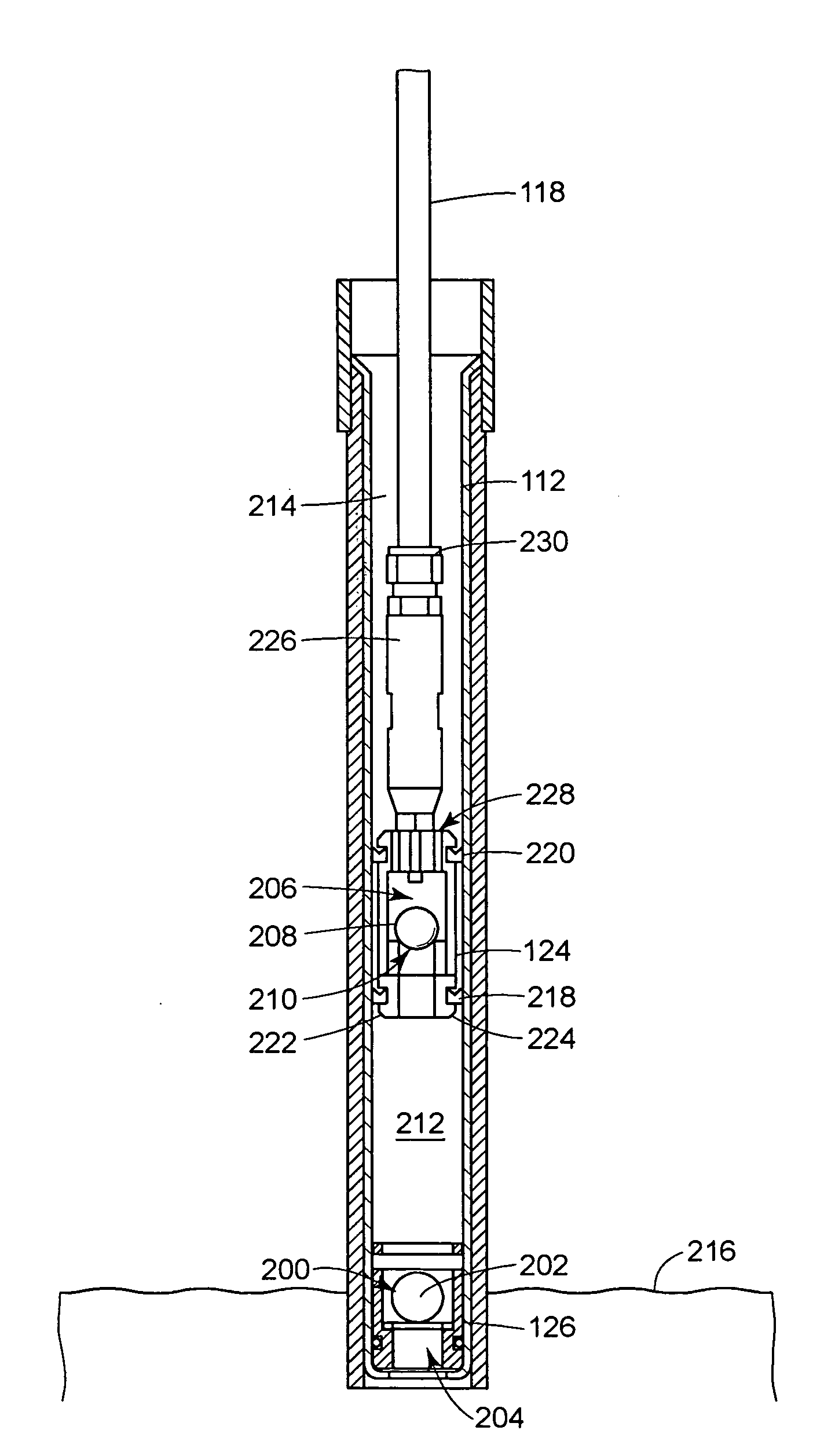
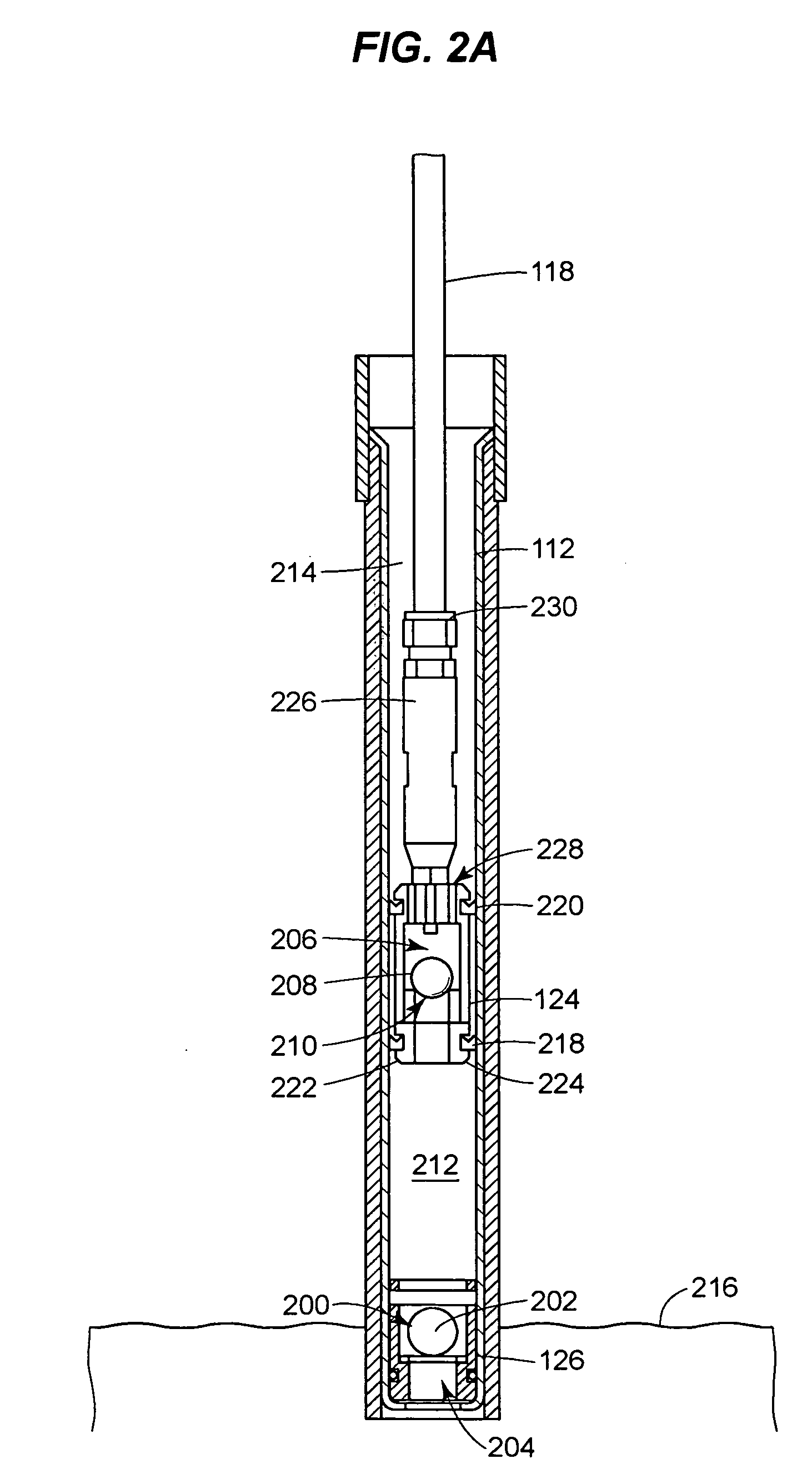
[0009]Provided are various techniques for forming a check valve in a drive piston valve or foot valve in a fluid pumping system, in particular a system for use in accessing underground fluids. Example applications include leachate removal from a landfill, oil and tar removal from petroleum or chemical facilities and clean up of remediation sites, and the like. The check valve may include a valve seat, or sealing plate, in the form of a non-compressible (e.g., metal or ceramic) sealing plate which is retained within the valve assembly by a compressible, resilient mating element. By forming the valve seat of a material (e.g., metal) different than the material of the valve assembly housing (e.g., a resin), the wear problems of conventional check ball engagement seals may be alleviated.
[0010]In some examples, the valve seat may have a truncated corner that forms the sealing engagement with a check ball. The truncated corner helps ensure a tight seal over a long lifetime by, for example, preventing chemical encrustation build-up or other containment at the sealing edge.

Problems solved by technology

This is particularly useful because in many applications the fluids being pumped can be hazardous to people and the environment, such as leachate removal from a landfill, oil and tar removal from petroleum or chemical facilities and clean up of remediation sites, tank farms, pipe lines, manufactured glass plant (MGP) sites, and caisson sumps.
Yet, it has been found that this inlet sealing still results in leakage in conventional systems.
For example, when using a resin material such as DELRIN (available from E.I. du Pont of Wilmington, Del.) for both the foot valve seat and drive piston, the stainless steel check balls do not form a tight seal throughout the life of the device.
With continual pumping, material build up on the inlet seal as well as material wear will scratch and groove the seal thus degrading performance of the check valve.
It has been found that over time when pumping gritty material and pumping at depths of 100′ or more the foot valve and drive piston leak at the check ball valve seat on both the drive piston and foot valve.

Method used


Image

  • Drive piston and foot valve seat
  • Drive piston and foot valve seat
  • Drive piston and foot valve seat

Examples


Embodiment Construction

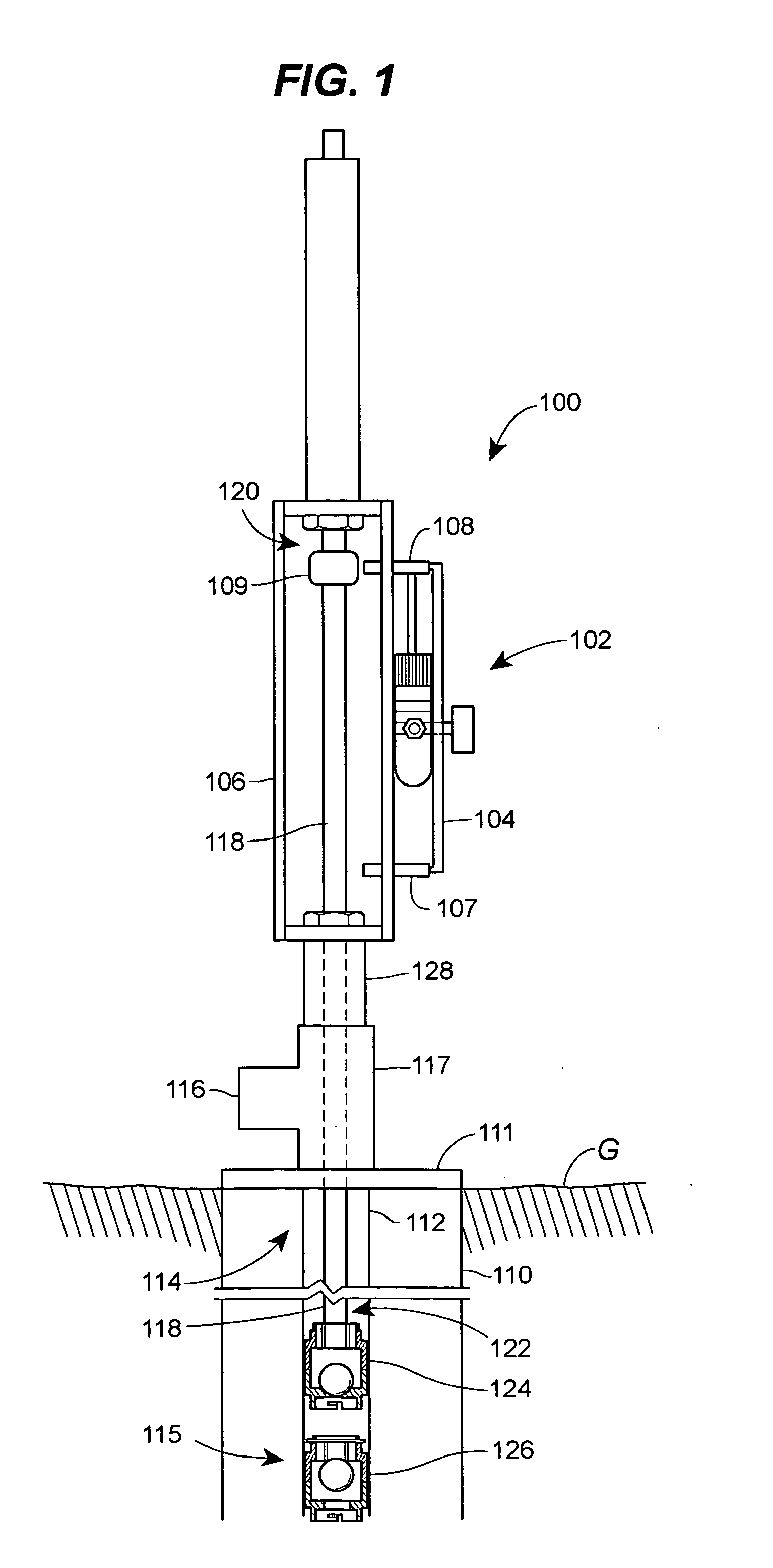
[0024]FIG. 1 illustrates a pumping system 100 that may be useful in pumping liquid, such as groundwater, hydrocarbons, tar, oil, chemicals or landfill leachate, through a well in a landfill or other geological site, for example, for collection analysis, consumption or disposal of the liquid. The system 100, of the illustrated example, has a drive motor assembly 102 having a piston pump actuator 104 mounted to a frame 106 (illustrated partially uncovered to display the inside) and with two limit switches 107, 108 for detecting a trigger element 109 for controlling operation of the drive motor 102. The drive motor assembly 102 is mounted to a drilled well casing 110 (illustrated partially uncovered to display the inside), via a well head 111, shown at the top surface (G) of a geological site. By way of example not limitation, the casing 110 may be formed of an organic polymer, such as polyvinyl chloride (PVC) or high density polyethylene (HDPE). Depending on the temperatures of the ap...


PUM

PropertyMeasurementUnit
Pressureaaaaaaaaaa
Flow rateaaaaaaaaaa

Abstract

A drive piston valve and a foot valve may each have a valve seat in the form of a non-compressible (e.g., metal or ceramic) sealing plate having a compressible, resilient mating element that retains the ring at an inlet portion of a check valve having a housing formed of another material, such as a low-wear resin material. In some examples, the sealing plate may have a truncated corner for engaging a check ball in its closed positioned while avoiding damage to the check ball or plate resulting from a chemical encrustation build-up or other containment at the sealing edge.

Description

FIELD OF THE DISCLOSURE [0001]The invention relates generally to devices and methods for pumping liquids and more particularly to devices and methods for pumping liquids from a well or a below-surface reservoir using a driving piston rod.BACKGROUND OF RELATED ART [0002]There are a variety of techniques for pumping fluids from underground reservoirs. Over a hundred years ago, general windmill and hand pump systems were developed to access well water for drinking and irrigation. Oil well piston pumps with top-head pump jacks were also developed to recover oil. These devices used top head drive piston pumps and stand pipes for the fluid discharge. This basic technology, albeit in more advanced forms, is still in use today. Of course today, pumping systems are used in a variety of applications and come in a variety of other forms.[0003]Both the water well and oil well top head drive piston pumps had to address the problem of discharge of liquid at the surface. The liquid discharge needs...

Claims


Application Information

Patent Timeline
IPC IPC(8): E21B43/00
CPCF04B47/02F04B53/1002F04B53/126F05C2203/08F05C2225/12F16K15/042E21B43/126
Inventor BERTANE, MARKMASSIE, STEVE
Owner BLACKHAWK TECH
Learn More