Magnetic Separation Method

a separation method and magnetic separation technology, applied in the direction of magnetic separation, solid separation, chemistry apparatus and processes, etc., can solve the problems of ineffective technique, inability to cleanly separate magnetic material from the drum, and substantial harm in any downstream processing of crushed rock feed, etc., to achieve increase separation, increase magnetic strength, and reduce magnetic strength

a separation method and magnetic separation technology, applied in the direction of magnetic separation, solid separation, chemistry apparatus and processes, etc., can solve the problems of ineffective technique, inability to cleanly separate magnetic material from the drum, and substantial harm in any downstream processing of crushed rock feed, etc., to achieve increase separation, increase magnetic strength, and reduce magnetic strength

US20080011650A1Active Publication Date: 2008-01-17GEKKO SYST PTY LTD

Image

  • Magnetic Separation Method
  • Magnetic Separation Method
  • Magnetic Separation Method

Examples


Embodiment Construction

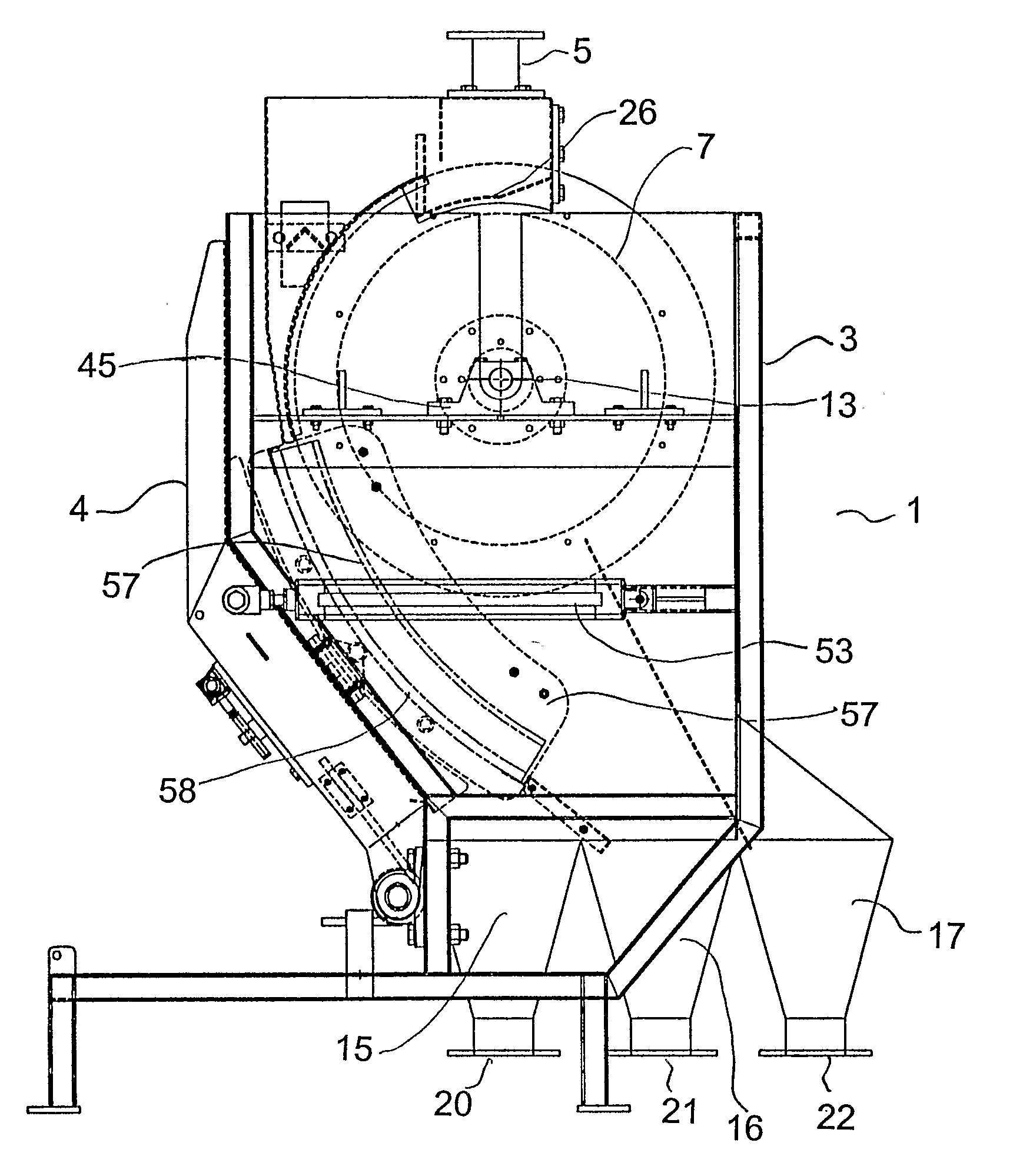
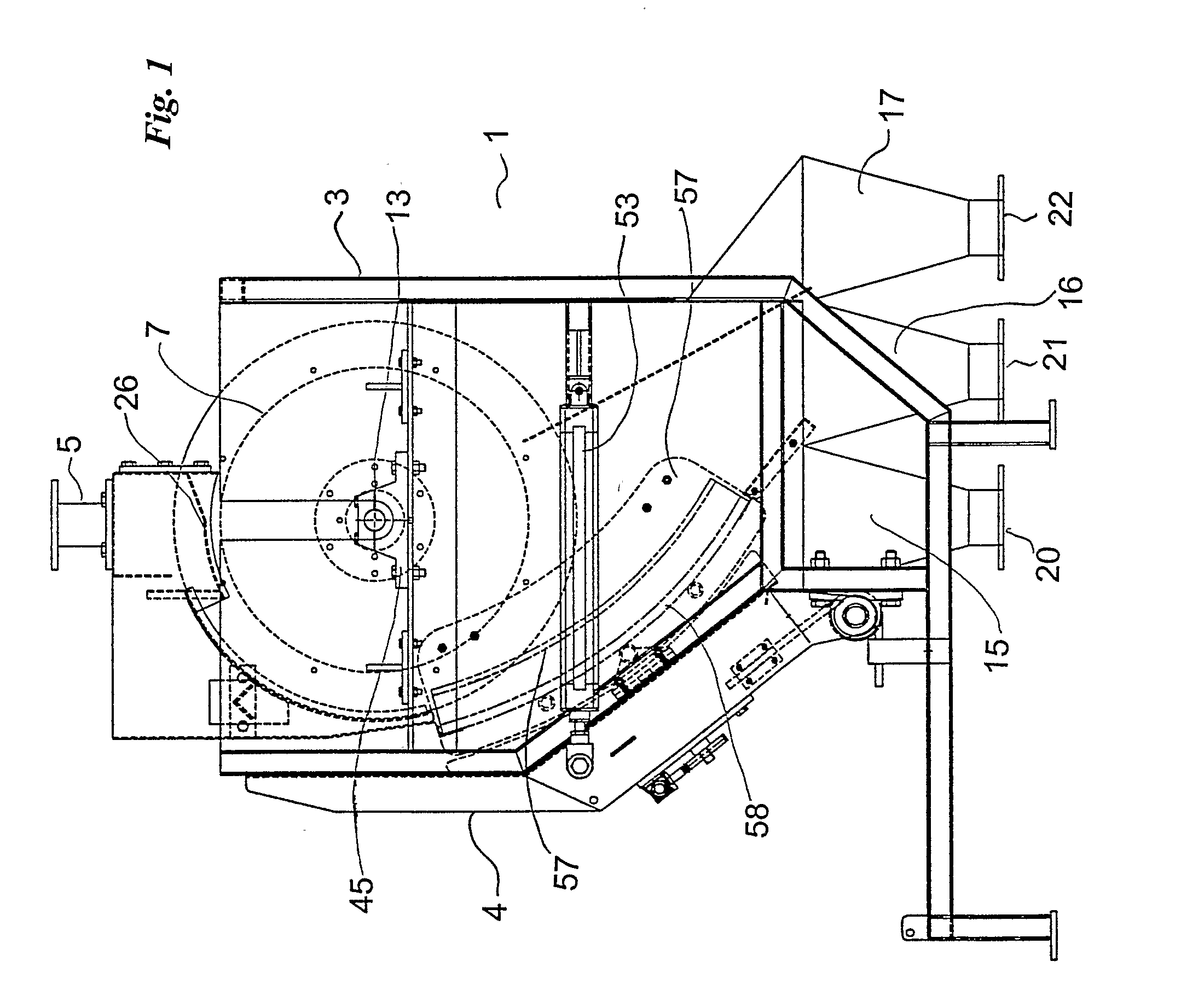
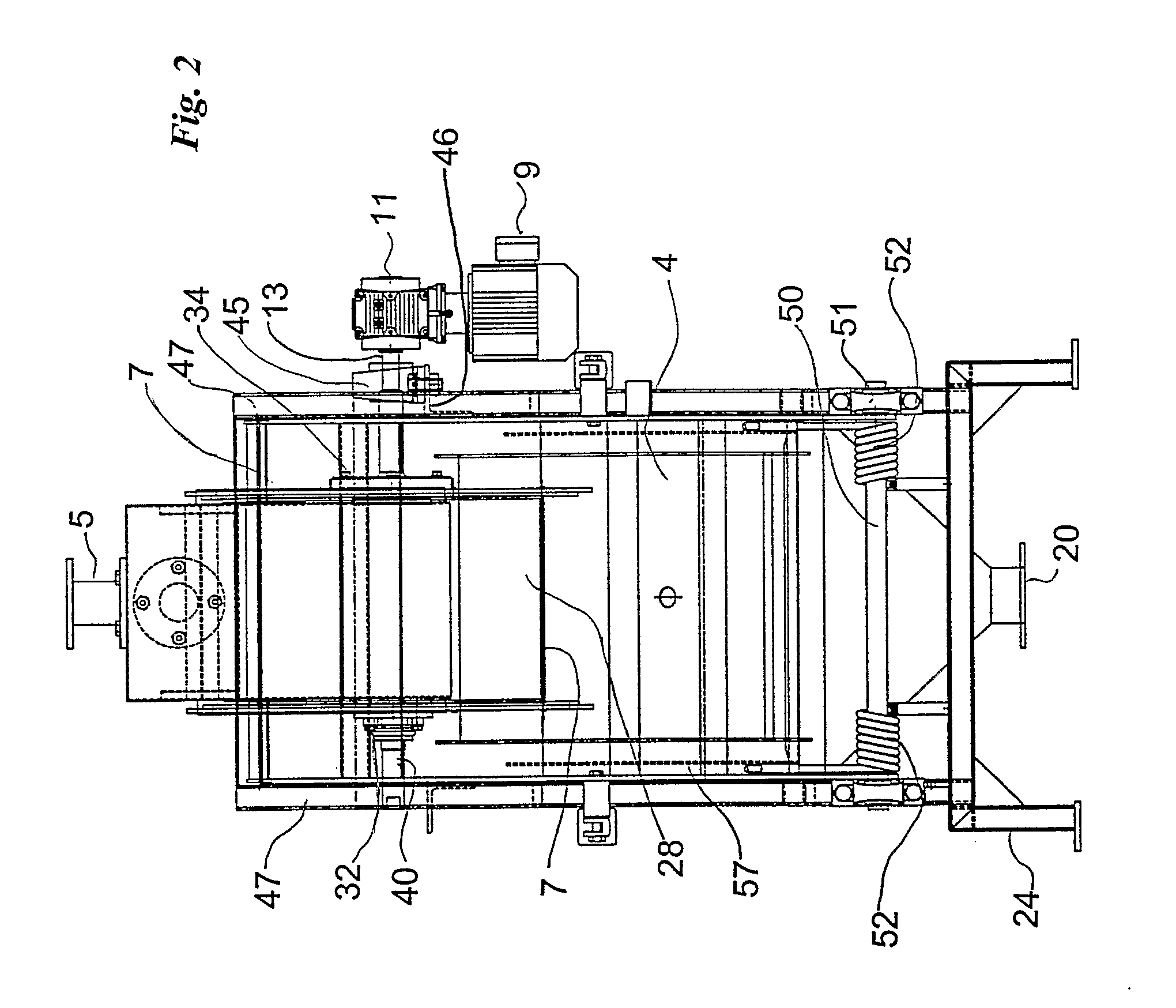
[0035] The various elements identified by numerals in the drawings are listed in the following integer list.

INTEGER LIST

[0036]1 Magnetic separator [0037]3 Housing [0038]4 Cover [0039]5 Inlet [0040]7 Drum assembly [0041]9 Motor [0042]11 Gear box [0043]13 Drive shaft [0044]15 Launder [0045]16 Launder [0046]17 Launder [0047]20 Outlet [0048]21 Outlet [0049]22 Outlet [0050]24 Support stand [0051]26 Flow plate [0052]27 Feed cover [0053]28 Drum [0054]30 Flange [0055]31 Cover [0056]32 Bearing [0057]33 Magnet assembly [0058]34 Outer plate [0059]35 Primary magnet element [0060]36 Secondary magnet element [0061]37 Tertiary magnet element [0062]38 Opening [0063]39 Mounting plate [0064]40 Stub shaft [0065]41 Hub [0066]42 Secondary stub shaft [0067]45 Mounting block [0068]46 Cross member [0069]47 Frame member [0070]50 Shaft [0071]51 Bearing [0072]52 Spring [0073]53 Pneumatic cylinder [0074]55 Sieve assembly [0075]57 Side wall [0076]58 Screen [0077]59 Frame [0078]60 Mesh elements [0079]61 Suppor...


PUM


Abstract

A magnetic separator for a mineral feed comprising, a rotatable drum having an attraction surface, an inlet for receiving a stream of the mineral feed and directing it past the rotating drum, means for generating a magnetic field to attract magnetic components in the feed to the attraction surface, a first zone for take off of non-magnetic components of the mineral feed, and a second zone for take off of the magnetic components, wherein the magnetic field generating means are adapted to subject the magnetic components to at least one reversal of polarity of the magnetic field as the drum rotates.

Description

FIELD OF THE INVENTION [0001] This invention relates to a method for separating magnetic material from a feed. It also relates to a magnetic separator construction for performing the method of the invention. BACKGROUND OF THE INVENTION [0002] In industries such as the mining industry where it is necessary to employ crushers to crush rocks, it is common place for pieces of magnetic material forming part of the crushing equipment to break off and be mixed with the crushed rock. This magnetic material, if it is left mixed with the crushed rock feed, can cause substantial harm in any downstream processing of the crushed rock feed. [0003] In many instances, magnetic separators are therefore employed immediately downstream of crushers to remove any magnetic material whether it has been broken off from the crushers during the crushing operation or incorporated from any other source. [0004] In the gold mining industry in particular, rock is crushed whilst being mixed with water to form a sl...

Claims


Application Information

Patent Timeline
17 Jan 2008
Publication
US20080011650A1
IPC
B03C1/247
CPC
B03C1/12; B03C1/247; B03C1/145
Inventors
LEWIS-GRAY, ALEXANDER HAMILTON