Dispensing devices, and systems

a technology of dispensing devices and systems, applied in the field of dispensing devices, can solve the problems of inconvenience in removing the spray head, consumers seem to lack interest in recharging spray bottles, and many consumers are unwilling to adopt such methods, so as to reduce assembly and the cost of making such an article in high volume, prevent damage or inadvertent opening, and ensure the effect of product stability

Inactive Publication Date: 2008-01-17
KLIMA WILLIAM L +1
View PDF40 Cites 19 Cited by
  • Summary
  • Abstract
  • Description
  • Claims
  • Application Information

AI Technical Summary

Benefits of technology

[0109] Preferably, the dispensers according to the present invention include a multiple-chamber component made as a single piece or integral unit. For example, this component is made as a single piece plastic injection molded article to reduce assembly and the cost of making such an article in high volume. More preferred embodiments of the dispensers according to the present invention include a multiple chamber component or container having a depth greater than a width thereof. In some of these more preferred embodiments, the height is significantly greater than the width of this particular component. In a most preferred embodiment thereof, the component has multiple chambers accessible from the top of the container, and is split into multiple chambers by one or more partitioning or dividing wall portions of the container. A particularly preferred embodiment utilizes a substantially cylinder or cup-shaped outer wall portion having one or more dividing wall portions to provide equally sized and shaped multiple compartments accessible from the top of the container. Preferably, this type of container includes an upper lip portion for a variety of various applications and combinations with closures. This particular embodiment allows for the use of a substantially cylindrical shaped closure (e.g. snap cap, threaded cap, lid, etc.), which allows for a tight and evenly distributed seal around the perimeter thereof with the cylindrical or cup-shaped container.
[0110] In some embodiments of the containers according to the present invention, the top wall portions and/or bottom wall portions can provide access to the multiple compartments or chambers within the container. In some applications, these wall portions are defined by sealing membranes (e.g. heat sealed and/or inductive sealed to the plastic injection molded container), or are openable, breakable or frangible wall portions of the plastic injection molded container itself. In some preferred embodiments, the membranes are provided with an additional protective seal or cap so as to prevent damage or inadvertent opening of the container during shipping, handling and/or storing. Thus, in some preferred embodiments, the product is doubly, triply or even more packaged to prevent leakage, decomposition of the products, oxidation, protection of the product to provide long shelf life and stability of the product contained therein.
[0111] In some of the most preferred embodiments, the multiple chamber or compartment container is configured as a cartridge or insert for use in a dispensing container or package. In this manner, the cartridge containing product, after its contents have been consumed, can be replaced with another cartridge or insert within the same dispensing container or package to allow recharging or reuse of the original dispenser. In this man

Problems solved by technology

However, many consumers are unwilling to adopt such methods apparently due to some inconvenience in the steps involved with the recharging process of the spray bottles.
In particular, there is some inconvenience in removing the spray head, opening the chemical concentrate container, pouring the chemical concentrate into the empty spray bottle, adding water, and reattaching the spray head to the bottle.
Further, consumers apparently lack interest in recharging spray bottles due to some reluctance based on their inexperience and knowledge in mixing and diluting liquids, which is done by processing chemists for the bottlers.
In addition, recharging is usually a messy undertaking due to spillage of chemical concentrate while pouring from one container to the other, overfilling, accidentally knocking over the bottle being filled due to its instability when unfilled, and other undesirable mishaps that can occur, that provide substantial inconveniences.
Importantly, sizea

Method used


Image

  • Dispensing devices, and systems
  • Dispensing devices, and systems
  • Dispensing devices, and systems

Examples


examples

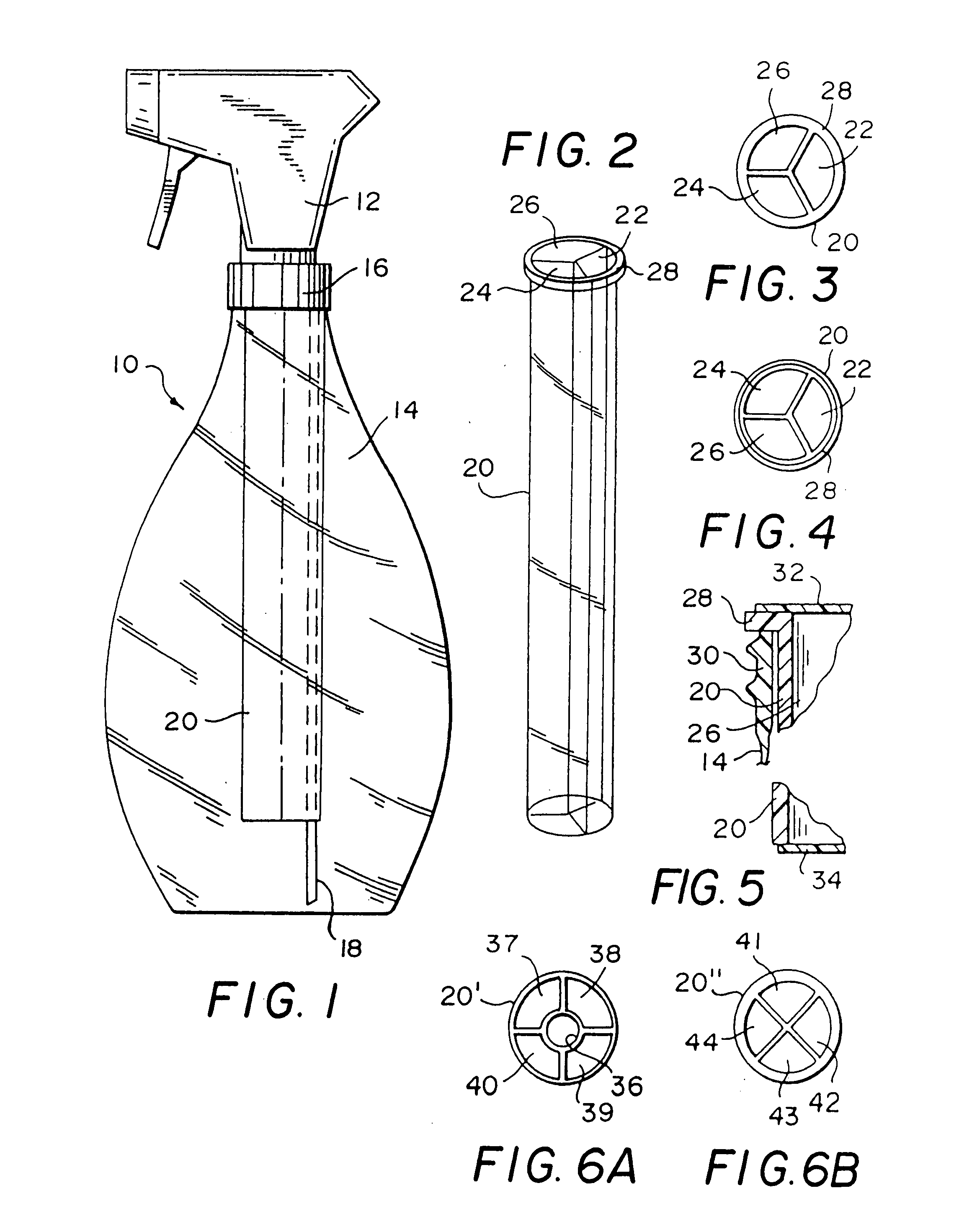
[0400] I. Cold Ice Tea Product. A cartridge of the type shown in FIG. 6A can be used for making a cold ice tea beverage. Specifically, a liquid ice tea concentrate is stored in one (1) reservoir, a liquid or powder sugar is stored in two (2) reservoirs, and a liquid flavoring (e.g. lemon, raspberry, peach, etc.) is stored in one (1) reservoir. The cartridge can be used in the dispenser shown in FIG. 93 or FIG. 96. The user accesses only the one reservoir containing liquid ice tea concentrate to make an unsweetened ice tea beverage. The user can also decide to selectively add one or two reservoirs of sweeter depending on taste, and optionally selectively add the liquid flavoring again depending on taste. Cold water and ice can be added to the dispenser to complete the mixture by shaking.

[0401] II. Hot Coffee Product. A cartridge of the type shown in FIG. 6A can be used for making a cold ice tea beverage. Specifically, a liquid coffee concentrate is stored in one (1) reservoir, a liq...


PUM

PropertyMeasurementUnit
Plasticityaaaaaaaaaa

Abstract

Rechargeable containers and dispensers, in particular a product dispenser, including at least one compartment for storing separately one or more products. Preferably, a container having multiple compartments for storing separately one or more products including a seal for sealing the multiple compartments and a lid connected to the container which can be removed.

Description

RELATED APPLICATIONS [0001] This application is a continuation-in-part (CIP) of the following U.S. Patent Applications: [0002] 1) “Container”, Ser. No. 10 / 071,224, filed on Feb. 1, 2002 (pending); [0003] 2) “Rechargeable Containers and Dispensers”, Ser. No. 09 / 192,317, filed on Nov. 16, 1998 (pending); [0004] 3) “Rechargeable Containers and Dispensers”, Ser. No. 08 / 897,838, filed on Jul. 21, 1997, and issued as U.S. Pat. No. 5,836,479; [0005] 4) “Rechargeable Dispensers”, Ser. No. 08 / 852,736, filed on May 7, 1997, and issued as U.S. Pat. No. 5,947,332; [0006] 5) “Multiple Neck Spray Bottle, and Methods of Making and Using”, Ser. No. 08 / 808,575, filed on Feb. 28, 1997 and issued as U.S. Pat. No. 6,319,453; [0007] 6) “Rechargeable Dispensers”, Ser. No. 08 / 694,386, filed on Aug. 8, 1996 (abandoned); [0008] 7) “Rechargeable Dispensers”, Ser. No. 08 / 507,691, filed on Jul. 25, 1995 (abandoned); [0009] 8) “Rechargeable Dispensers”, Ser. No. 08 / 485,254, filed on Jun. 7, 1995, and issued as ...

Claims


Application Information

Patent Timeline
IPC IPC(8): B67D5/56B67D5/52B67D5/40B67D7/74B05B11/00B29C49/04B29C49/06B65D1/02B65D1/20B67D7/58B67D7/70
CPCB05B11/0056B65D1/20B05B11/0083B05B11/0086B05B11/0097B05B11/3057B05B11/3081B29C49/04B29C49/06B29C2049/048B29C2049/5837B29C2793/009B29K2023/06B29K2023/12B29K2027/06B29K2067/00B29L2031/7158B65D1/023B05B11/0081B29C49/04108B05B11/1057B05B11/1081B29C2949/0715
Inventor KLIMA, WILLIAM L.KLIMA, WALTER F. JR.
Owner KLIMA WILLIAM L
Why Eureka
Try Eureka