Radiation imaging apparatus, apparatus control method, and computer-readable storage medium storing program for executing control

a technology of radiography and control method, applied in the direction of radiography controlled devices, instruments, television systems, etc., can solve the problems of inadequacies of high-speed radiography, heat generation from radiation sources, and power consumption soar, so as to reduce the dose of radiation exposure and suppress heat generation

Active Publication Date: 2008-01-17
CANON KK
View PDF25 Cites 56 Cited by
  • Summary
  • Abstract
  • Description
  • Claims
  • Application Information

AI Technical Summary

Benefits of technology

[0009]Generally, when fluoroscopic radiographing is performed, a pulse generating radiation source is used to reduce the dosage of exposure to radiation for a patient. The source can be of a rotating anode type capable of suppressing heat generation by rotating an anode member called a target for triggering off collision between accelerated electrons for generation of X-rays, and of a fixed anode type without rotation. The X-ray generation apparatus (radiation source) of the rotating anode type can generate X-rays of high dosage, and is appropriate for high-speed fluoroscopic radiographing. By contrast, since the X-ray generation apparatus of the fixed anode type cannot generate large amount of X-rays instantaneously, it is not appropriate for high-speed radiographing.

Problems solved by technology

By contrast, since the X-ray generation apparatus of the fixed anode type cannot generate large amount of X-rays instantaneously, it is not appropriate for high-speed radiographing.
In any case, there is the problem of heat generation from a radiation source because it is necessary to irradiate an object with plural times of emission of X-ray pulses for several seconds to several minutes, or for a longer time, in fluoroscopic radiographing.
Then, the power consumption soars, and the problem of heat generation from the flat panel X-ray detector arises.

Method used


Image

  • Radiation imaging apparatus, apparatus control method, and computer-readable storage medium storing program for executing control
  • Radiation imaging apparatus, apparatus control method, and computer-readable storage medium storing program for executing control
  • Radiation imaging apparatus, apparatus control method, and computer-readable storage medium storing program for executing control

Examples


Embodiment Construction

[0048]The mode for embodying the present invention is practically described below by referring to the attached drawings.

(First Mode for Embodying the Present Invention)

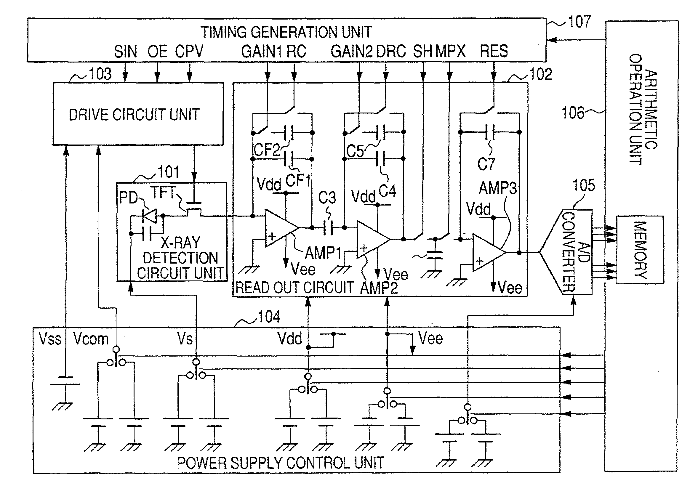
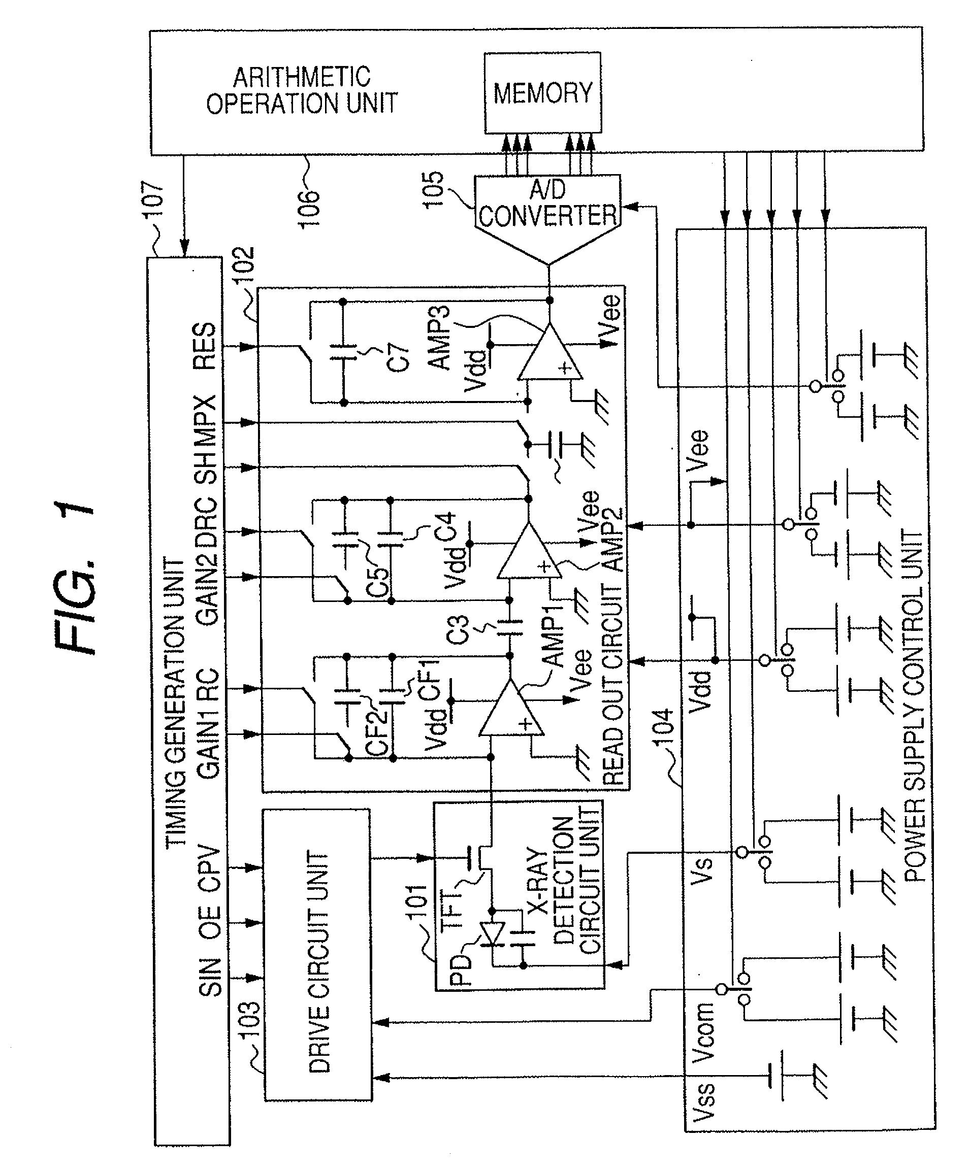
[0049]FIG. 1 illustrates the configuration of the circuit of the flat panel X-ray detector (radiation imaging apparatus) according to the first mode for embodying the present invention. A picture element 101 is configured mainly by an optoelectronic conversion element (PD), and a switch element (TFT). The PD can be an X-ray detection element for converting an X-ray directly into electric charge or a photodiode for converting visible light into charge. When it is a photodiode, a phosphor (not illustrated in the attached drawings) for temporarily converting an X-ray into visible light is required. The optoelectronic conversion element PD is biased by the voltage Vs from a power supply control unit 104, and the gate voltage of the TFT is driven by the signal from a drive circuit unit 103. The drive circuit unit 103 is a ...


PUM


Abstract

To provide a radiation imaging apparatus which is capable of both connecting state radiographing for radiographing with a C arm connected and non-connecting state radiographing for radiographing with the C arm disconnected, and is convenient and obtains high quality images, the apparatus includes: a flat panel detector; a holding unit for holding at least the flat panel detector;and a control unit for controlling the flat panel detector. With the configuration, the flat panel detector can be connected to and disconnected from the holding unit; connecting state radiographing can be performed with the flat panel detector connected to the holding unit, and non-connecting state radiographing can be performed with the flat panel detector disconnected from the holding unit; the control unit controls the flat panel detector such that a heat generation quantity of the flat panel detector during the non-connecting state radiographing can be lower than a heat generation quantity of the flat panel detector during the connecting state radiographing.

Description

BACKGROUND OF THE INVENTION[0001]1. Field of the Invention[0002]The present invention relates to a radiation detection system for use in diagnoses in a hospital, and a radiation imaging apparatus appropriate as an industrial non-destructive inspection apparatus. In this specification, electromagnetic waves such as X-rays, γ-rays, etc., α-rays, and β-rays are included in radiation.[0003]2. Description of the Related Art[0004]With the progress of recent thin film semiconductor processing technology for radiography, apparatuses have been developed for radiographing an X-ray image using a semiconductor sensor. These X-ray detectors can be produced in a relatively flat structure, and is referred to as a flat panel X-ray detector (flat panel detector) (FPD). The FPD can be an indirect FPD and a direct FPD. The indirect FPD converts X-rays into visible light through a phosphor, and detects the light using an amorphous optoelectronic conversion element and a switch element. The direct FPD d...

Claims


Application Information

Patent Timeline
Patent Type & Authority Applications(United States)
IPC IPC(8): G01T1/24A61B6/00G01T1/20G01T7/00G03B42/02H04N5/32H04N5/335H04N5/345H04N5/357H04N5/369H04N5/374H04N5/378
CPCA61B6/4441A61B6/548A61B6/4405A61B6/4488H04N5/32H04N25/709
Inventor ENDO, TADAOKAMESHIMA, TOSHIOYAGI, TOMOYUKITAKENAKA, KATSUROYOKOYAMA, KEIGO
Owner CANON KK
Why Eureka
Try Eureka