Wave energy converter with air compression (WECWAC)

a technology of air compression and wave energy, applied in the direction of positive displacement liquid engines, electric generator control, machines/engines, etc., can solve the problems of long life, low cost, and significant challenges in efficiently harnessing ocean wave energy, and achieve the effects of simple design, and reducing the size/volume of the upper chamber

Inactive Publication Date: 2008-01-17
OCEAN POWER TECHNOLOGIES
View PDF18 Cites 41 Cited by
  • Summary
  • Abstract
  • Description
  • Claims
  • Application Information

AI Technical Summary

Benefits of technology

[0008] An important aspect of the invention is that the piston stroke is variable. The buoyancy of the spar is set so that in still water (i.e., low amplitude waves), the spar drifts down and sits low in the water, with only the top part of the cylinder above water. The downward drift of the cylinder (as shown in FIG. 1B) causes the size/volume of the upper chamber to be decreased. As waves increase in height, the WEC begins to compress air in the upper chamber of the cylinder and the spar begins to rise out of the water under the force generated during compression. As waves build up, air is also compressed in the lower chamber of the cylinder. There is thus provided a variable stroke operation which makes the operation of the system much more effective. Unlike previous inventions, the proposed system is very simple in design, yet it is able to dynamically adapt itself to different wave conditions. In the event of excessive stroke, bumpstops (or air springs) are used to prevent direct contact between the cylinder heads and the piston faces.
[0009] According to an aspect of the invention, the float is made with hollow sections for receiving and processing compressed air. Following compression in the cylinder(s), the pressurized air is pumped into the hollow float, which therefore doubles as an air receiver/accumulator. This larg...

Problems solved by technology

There are many significant challenges in harnessing ocean wave energy effectively.
Furthermore, unlike tidal or wind energy, fluid motion is not continuous in direction, with waves rising and falling over a short time period.
Therefore a major challenge is to find apparatus that will efficiently convert wave energy into a form that can be efficiently used, e.g., to drive an electric generator.
However, th...

Method used


Image

  • Wave energy converter with air compression (WECWAC)
  • Wave energy converter with air compression (WECWAC)
  • Wave energy converter with air compression (WECWAC)

Examples


Embodiment Construction

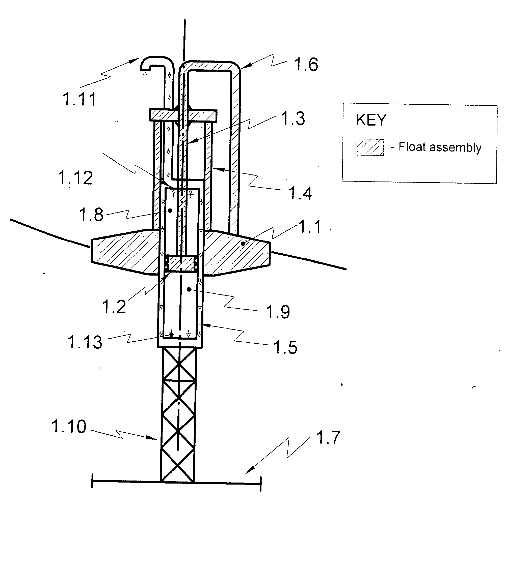
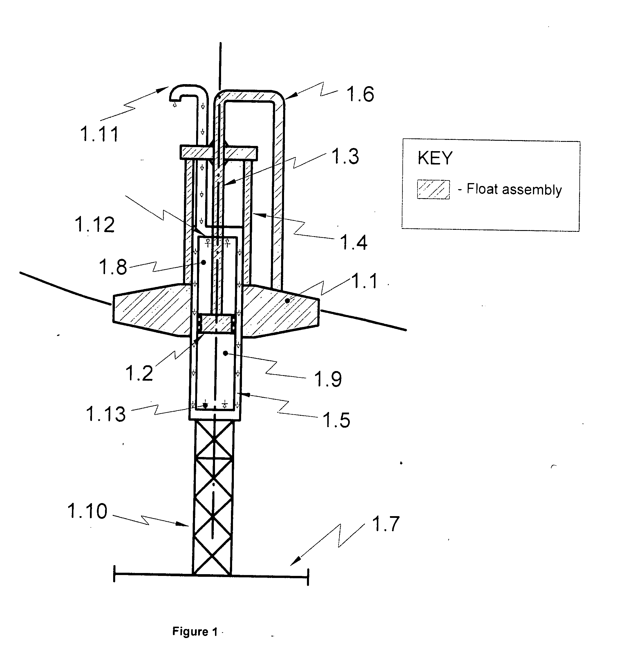
[0016] Referring to FIG. 1, there is shown a highly simplified diagram of a WECWAC embodying the invention. The WECWAC includes a float 1.1 and a central spar 1.10. Mounted above the central spar 1.10 is a cylinder body 1.5 and attached to the bottom of the central spar 1.10 is a heave plate 1.7. The float 1.1 defines a first floating body which is designed to move in phase with the waves. The float can be any shape. In a preferred embodiment, the float is toroidal with a central opening shaped to allow it to move up and down relative to the centrally located spar. The spar 1.10 with the cylinder 1.5 and the heave plate 1.7 defines a second floating body which is generally designed to move out of phase with the waves. The first and second floating bodies thus tend to move out of phase relative to each other. Each floating body is able to move independently of the other, with only air pressure and friction linking the two.

[0017] The float 1.1 is connected via a bridge 1.4 to a pisto...


PUM


Abstract

A wave energy converter with air compression (WECWAC) includes a cylinder and a piston located within the cylinder dividing the cylinder into an upper chamber and a lower chamber. The cylinder is fixedly attached to a spar whose up/down (heave) motion is restrained. The piston is fixedly attached to, and driven by, a float which moves generally in phase with the waves. Under typical wave conditions the piston functions to compress air within the upper chamber on its up stroke and within the lower chamber on its down stroke, i. e., the system is thus double-acting. In still water, the spar and cylinder combination is designed to drift down into the body of water relative to the piston whereby the size/volume of the upper chamber is decreased (while that of the lower chamber is increased). For small amplitude waves the piston continues to compress air in the upper chamber and this asymmetrical compression continues until the waves reach a predetermine level when “double-action” is resumed. Controlling the position of the cylinder relative to the piston enables the WECWAC to automatically regulate its compression ‘stroke’ to suit varying wave conditions. The pressurized air from a WECWAC may be stored and/or processed to drive a turbo-generator or it may be combined with the outputs of other WECWACs to drive a single large and highly efficient turbo-generator.

Description

[0001] This invention claims priority from U.S. provisional application Ser. No. 60 / 800,696 titled POWER GENERATION USING WAVE ENERGY AND PNEUMATIC TRANSMISSION filed May 16, 2006.BACKGROUND [0002] This invention relates to wave energy converters (WECs) for converting energy contained in surface waves on bodies of water into useful energy, e.g., to eventually generate electric power, and to a means for combining the outputs of a plurality of WECs and transmitting the combined output in a practical and efficient manner. [0003] There are many significant challenges in harnessing ocean wave energy effectively. Wave energy is highly variable in frequency and force. The frequency of the waves is generally very low and the force of the waves varies over a wide range (from low to very high). Furthermore, unlike tidal or wind energy, fluid motion is not continuous in direction, with waves rising and falling over a short time period. On the other hand, known efficient electric generators are...

Claims


Application Information

Patent Timeline
IPC IPC(8): F03B13/12
CPCF03B13/187F03B13/1875F03B13/24F03B13/20Y02E10/38Y02E10/30
Inventor BUFFARD, KEITHDRAPER, MARK R.PULLEN, KEITH ROBERTRHODES, ROBIN
Owner OCEAN POWER TECHNOLOGIES
Why Eureka
Try Eureka