Supercharge Your Innovation With Domain-Expert AI Agents!

Duty Cycle Correction Circuit Whose Operation is Largely Independent of Operating Voltage and Process

a duty cycle correction and operating voltage technology, applied in pulse manipulation, pulse duration/width modulation, pulse technique, etc., can solve the problems of different problems in the accuracy of clock signals, clock skew becomes an ever-increasing problem, and tolerability is necessarily diminished, so as to achieve a smaller change in the dcc correction range and be more tolerant.

Inactive Publication Date: 2008-01-17
GLOBALFOUNDRIES INC
View PDF21 Cites 14 Cited by
  • Summary
  • Abstract
  • Description
  • Claims
  • Application Information

AI Technical Summary

Benefits of technology

[0035]The first linear resistor may operate on a signal output by the first P-type FET to thereby pull-up a pulse width of the signal output by the first P-type FET and thereby decrease a duty cycle of the signal output by the P-type FET. The second linear resistor may operate on a signal output by the first N-type FET to thereby pull-down a pulse width of the signal output by the first P-type FET and thereby increase a duty cycle of the signal output by the N-type FET.
[0044]The first linear resistor may operate on a signal output by the first P-type FET to thereby pull-up a pulse width of the signal output by the first P-type FET and thereby decrease a duty cycle of the signal output by the P-type FET. The second linear resistor may operate on a signal output by the first N-type FET to thereby pull-down a pulse width of the signal output by the first P-type FET and thereby increase a duty cycle of the signal output by the N-type FET.

Problems solved by technology

As clock circuits improve and clock rates increase, tolerances are necessarily diminished, and clock skew becomes an ever-increasing problem.
Different problems can arise in the accuracy of the clock signal.
These networks can introduce duty cycle distortion due to circuit and interconnect modeling inaccuracies, process variations, and the environment.
For systems which use both the rising and falling edges for timing, a non-optimal clock duty cycle may require a lower clock frequency, reducing performance.
A duty cycle error of just 5% for instance (from 50% to 45%) may require a system clock to run at a maximum speed that is 10% lower, causing a significant impact on system performance.
Actual duty cycles typically do not have precisely the desired value.
While a duty cycle correction (DCC) circuit using the topology arrangement shown in FIG. 1A or FIG. 2A may display excellent granularity and linearity, it also displays very strong undesirable dependence on process and operating voltage conditions.
Having a fixed duty cycle may not necessarily result in optimal operating conditions in all applications.

Method used


Image

  • Duty Cycle Correction Circuit Whose Operation is Largely Independent of Operating Voltage and Process
  • Duty Cycle Correction Circuit Whose Operation is Largely Independent of Operating Voltage and Process
  • Duty Cycle Correction Circuit Whose Operation is Largely Independent of Operating Voltage and Process

Examples


Embodiment Construction

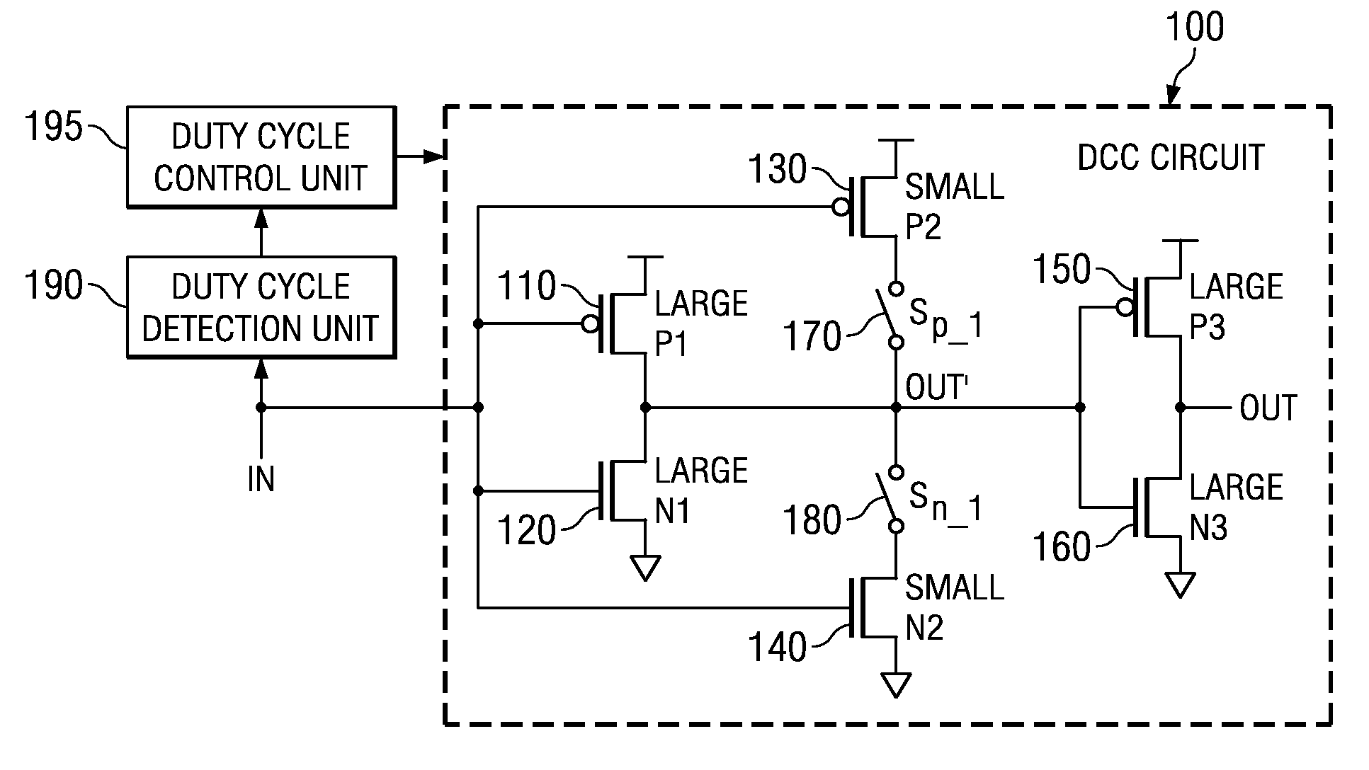
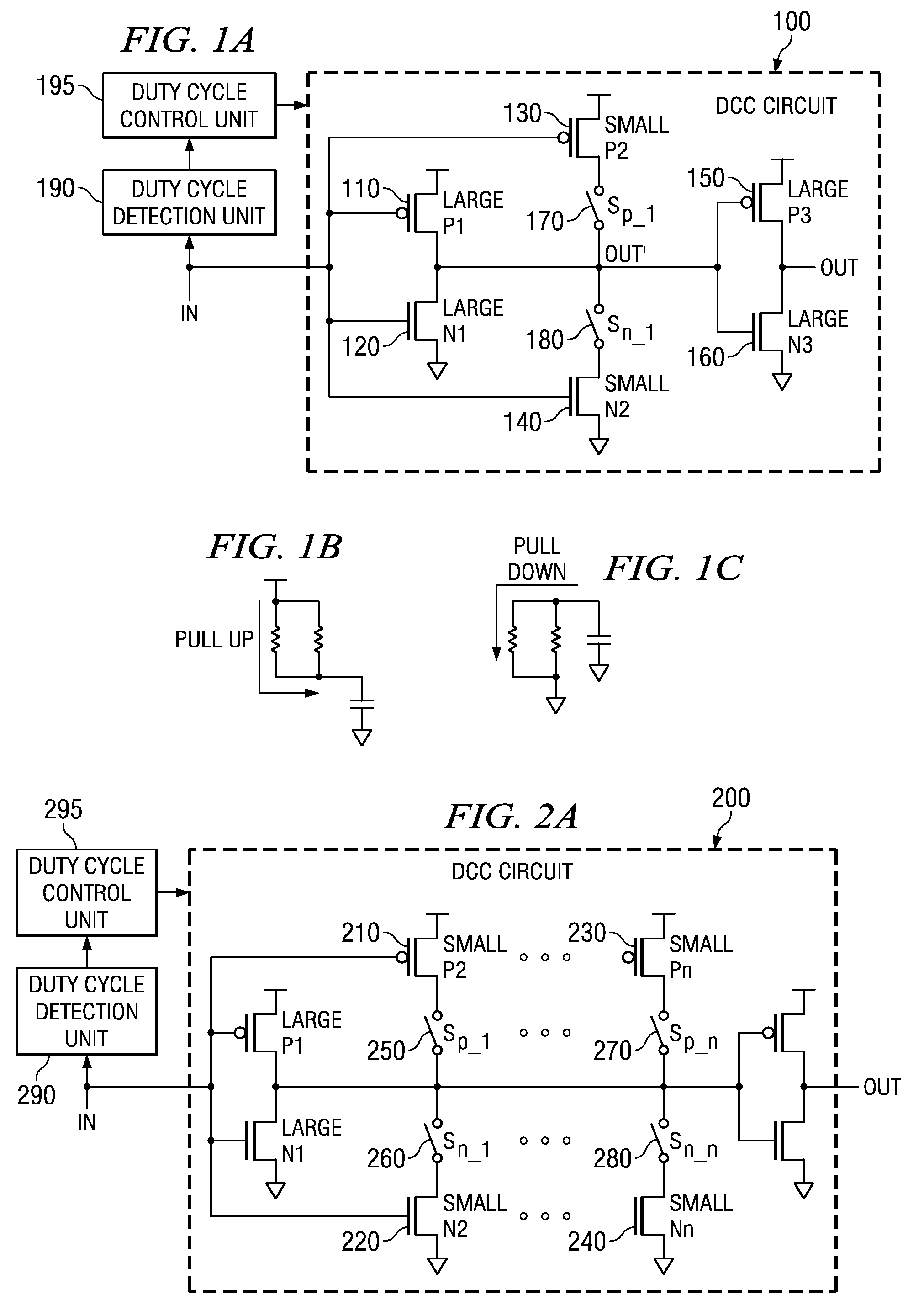
[0061]The illustrative embodiments provide a duty cycle correction (DCC) circuit that utilizes linear resistors rather than FETs to provide the duty cycle correction. Since the linear resistors are less sensitive to operating voltage and process, the resulting DCC circuit is more tolerant of variations in operating voltage and process. One application of such a DCC circuit is to provide varying duty cycles and non-50% duty cycles to circuitry of a data processing device where such varying or non-50% duty cycles provide more optimal performance.

[0062]FIG. 4A is an exemplary diagram illustrating a duty cycle correction (DCC) circuit in accordance with one illustrative embodiment. As shown in FIG. 4A, the DCC circuit 400 includes a first pair of FETs comprising a first PFET 410 and a first NFET 420. The first pair of FETs are part of the inverter circuit that provides the duty cycle correction. The first PFET 410 and NFET 420 preferably have large resistance values. Again, the terms “l...


PUM


Abstract

A Duty Cycle Correction (DCC) circuit is provide in which pairs of field effect transistors (FETs) in known DCC circuit topologies are replaced with linear resistors coupled to switches of the DCC circuit such that when the switch is open, the input signal is routed through the linear resistors. The linear resistors are more tolerant of process, voltage and temperature (PVT) fluctuations than FETs and thus, the resulting DCC circuit provides a relatively smaller change in DCC correction range with PVT fluctuations than the known DCC circuit topology that employs FETs. The linear resistors may be provided in parallel with the switches and in series with a pair of FETs having relatively large resistance values. The linear resistors provide resistance that pulls-up or pulls-down the pulse width of the input signal so as to provide correction to the duty cycle of the input signal.

Description

BACKGROUND[0001]1. Technical Field[0002]The present application relates generally to an improved duty cycle correction circuit. More specifically, the present application is directed to a duty cycle correction circuit whose operation is largely independent of operating voltage and process.[0003]2. Description of Related Art[0004]Many modern electronic systems require a precise clock circuit for proper operation. For example, digital information processing equipment such as a computer must have an accurate and reliable clock source to control the various signals that are sent between the functional components of the computer. In such systems, it is very important that all of the components are properly synchronized to a common clock.[0005]Synchronous electronic equipment utilizes an oscillator circuit to produce a basic source frequency signal. This signal is in turn utilized to drive other circuitry (such as a phase-lock loop, or PLL) for developing desired rise and fall times of sq...

Claims


Application Information

Patent Timeline
IPC IPC(8): H03K3/017
CPCH03K5/1565
Inventor BOERSTLER, DAVID W.HAILU, ESKINDERQI, JIEMING
Owner GLOBALFOUNDRIES INC
Features
  • R&D
  • Intellectual Property
  • Life Sciences
  • Materials
  • Tech Scout
  • Unparalleled Data Quality
  • Higher Quality Content
  • 60% Fewer Hallucinations
Learn More