Current monitoring device for high voltage electric power lines

a technology of current monitoring and electric power lines, applied in the direction of electric devices, process and machine control, frequency-division multiplex, etc., can solve the problems of inaccurate measurement, high cost of high-voltage devices, and insulate the current sensor for high-voltage,

Inactive Publication Date: 2008-01-17
SSI POWER LLC
View PDF7 Cites 29 Cited by
  • Summary
  • Abstract
  • Description
  • Claims
  • Application Information

AI Technical Summary

Benefits of technology

[0007]The present invention meets the needs described above through an electric power monitoring and response system for phase conductors of one or more multi-phase power lines that uses electromagnetic field sensors, such as inexpensive electric wire coils, located within one or more grounded housings positioned within the combined electromagnetic fields generated by the phase conductors. The system also includes electronics, typically located within the grounded housings, defining impedance networks that combine the measurements received from the electromagnetic field sensors to create output signal indicative of electric current values for the phase conductors. The housings can be conveniently attached and electrically grounded to the type of high voltage power line support commonly found in transmission and distribution substations.

Problems solved by technology

While very accurate, these devices are quite expensive when applied at high voltages.
This results, in large part, from the need to insulate the current sensors for high-voltage, which is quite expensive for voltages above 1,000 volts.
In multiphase applications, this technique is complicated by electromagnetic field interference from the adjacent phases, which results in inaccurate measurements.
This approach also requires expensive high-voltage insulation for the electromagnetic field sensors, which makes the system economically feasible only in limited situations.
While this technique reduces the difficulty of insulating the current sensor at high voltages, the sophisticated decoding technology required to turn the polarization measurement into a current measurement is quite expensive.
Again, this approach is economically feasible only in limited situations, for example at the highest transmission line voltages.
Another type of power system unknown occurs because high currents and ambient air heat the electric conductors, which causes them to stretch and sag from their overhead supports.
If this sag becomes too large, a voltage breakdown and resulting flash over can occur between the power line and another object, such as a tree or hill.
But these algorithms only produce estimates of the physical sag at critical locations that can vary significantly from the actual conditions due to voltage drop and reactive power loading on the lined during high load conditions.
But these optical systems are very expensive, do not work well in the dark, can be adversely affected by bad weather and fouling by grime, bird droppings and the like.
Although this patent describes the fundamental technology, it does not address specific configurations and refinements of the electric power monitoring and response system, such as those suitable for adapting the system for installation high voltage power line support structures, such as those found in transmission and distribution substations.

Method used


Image

  • Current monitoring device for high voltage electric power lines
  • Current monitoring device for high voltage electric power lines
  • Current monitoring device for high voltage electric power lines

Examples


Embodiment Construction

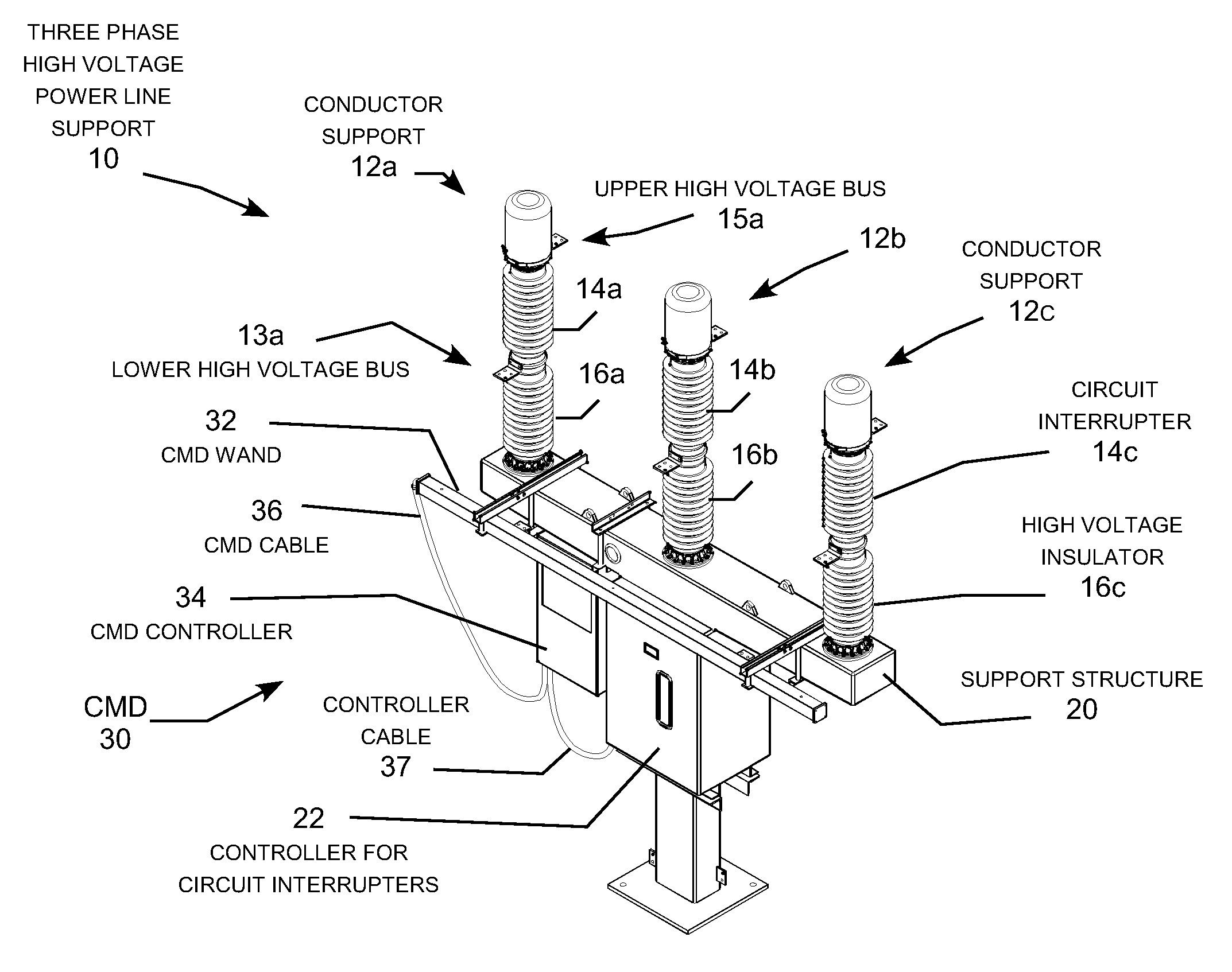
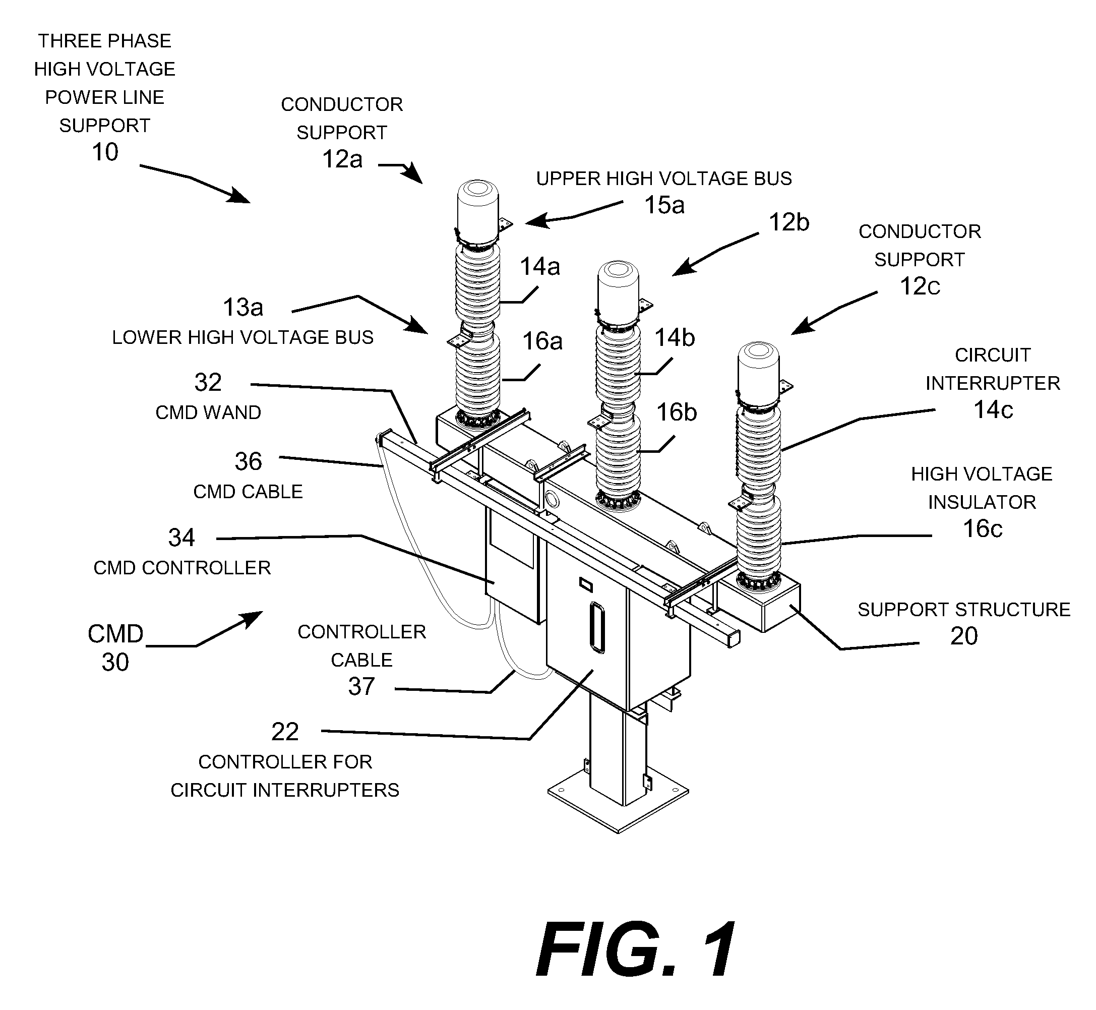
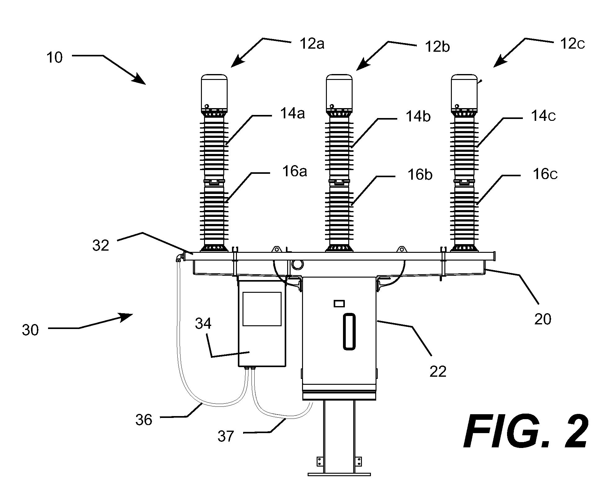
[0030]The present invention provides significant improvements in the electric power monitoring and fault protection equipment for multi-phase electric power lines described in U.S. Pat. No. 7,191,074, which is incorporated herein by reference. In particular, the improved electric power monitoring and response system includes a current monitoring device (“CMD”) in which a set of electromagnetic sensors located within one or more electrically grounded, non-electromagnetic housings. The grounded housings may also contain electronics defining impedance networks for combining the measurements from the sensors into current values. Placing the electromagnetic sensors and electronics within a grounded housing forms a modular unit typically referred to as a “wand” that can be easily attached to a strategically located structure within the electromagnetic field of a high voltage power line. For example, one or more CMD wands can be conveniently attached directly to the support structure for a...


PUM


Abstract

A current monitoring device (CMD) with a set of electromagnetic field sensors located within one or more grounded housings positioned within the combined electromagnetic fields generated by one or more electric power lines. The CMD includes electronics, typically located within the grounded housings, defining impedance networks that combine the measurements received from the field sensors to create output signal indicative of electric current values for the phase conductors. The housings can be conveniently attached and to transmission line towers, distribution line poles, and high voltage power line supports in transmission and distribution substations. The CMD controls response equipment, such as a circuit interrupter that responds to current disturbances detected by the CMD. The CMD may also include communication for sending the current values to a remote controller, such as a central control station, that implements a wide range of response equipment.

Description

REFERENCE TO RELATED APPLICATION[0001]This application claims filing priority to U.S. Provisional Patent Application Ser. No. 60 / 819,516 filed Jul. 10, 1006, which his incorporated herein by reference. The application also incorporates by reference U.S. Pat. No. 7,191,074 entitled “Electric Power Monitoring And Response System” granted Mar. 13, 2007; U.S. Pat. No. 7,078,643 entitled “Capacitor Switch With Internal Retracting Impedance Contactor” granted Jul. 18, 2006; and U.S. Pat. No. 6,236,010 entitled “Circuit Interrupter Including a Penetrating Electrical Contact With Grip and Release Structure” granted May 22, 2001.TECHNICAL FIELD[0002]The present invention relates to the field of high voltage electric power transmission and distribution systems and, more particularly, to an electric power monitoring and response system that uses a current monitoring device with electromagnetic field sensors located within a grounded housing to determine the phase currents in an electric power ...

Claims


Application Information

Patent Timeline
Patent Type & Authority Applications(United States)
IPC IPC(8): G08B21/00H02H7/00
CPCG01R1/04G01R19/2513G01R15/14
Inventor ROSTRON, JOSEPH R.
Owner SSI POWER LLC
Why Eureka
Try Eureka