Directional alignment and alignment monitoring systems for directional and omni-directional antennas based on solar positioning alone or with electronic level sensing

a technology of solar positioning and monitoring system, applied in the direction of antenna details, differentially interacting antenna combinations, antennas, etc., can solve the problems of no devices that can be remotely controlled, hands-on alignment of antennas is a significant cost to the owners of directional and omni-directional antennas, and there is no all-inclusive method to double check the audit of antenna alignments made by tower crews

Inactive Publication Date: 2008-01-17
SUNSIGHT HLDG
View PDF21 Cites 24 Cited by
  • Summary
  • Abstract
  • Description
  • Claims
  • Application Information

AI Technical Summary

Benefits of technology

[0011]The present invention frequently checks the alignment of an antenna automatically. No personnel must climb a tower or pole to physically take measurements to align an antenna and no personnel need be in the area of the antenna to check alignment. Alignment is checked independently of signal strength, which can eliminate a source of antenna malfunctio

Problems solved by technology

No devices are currently known that can be remotely controlled to monitor antenna alignment after installation.
Hands on alignment of antennas is a significant cost to the owners of directional and omni-directional antennas and accurate alignment information is crucial when relating to overall radio frequency (RF) system design and function.
Currently, there is no all inclusive method to double

Method used


Image

  • Directional alignment and alignment monitoring systems for directional and omni-directional antennas based on solar positioning alone or with electronic level sensing
  • Directional alignment and alignment monitoring systems for directional and omni-directional antennas based on solar positioning alone or with electronic level sensing
  • Directional alignment and alignment monitoring systems for directional and omni-directional antennas based on solar positioning alone or with electronic level sensing

Examples


Embodiment Construction

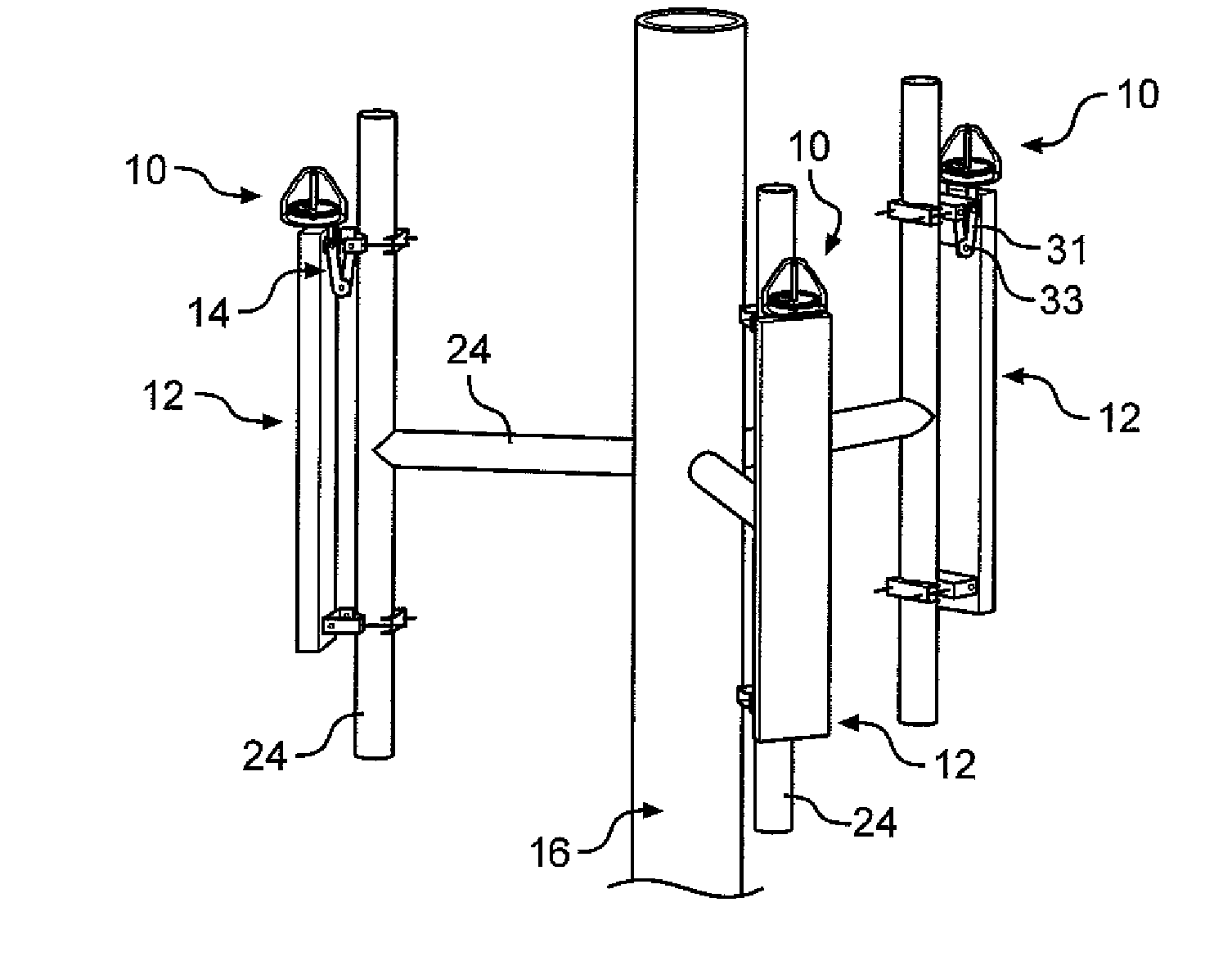
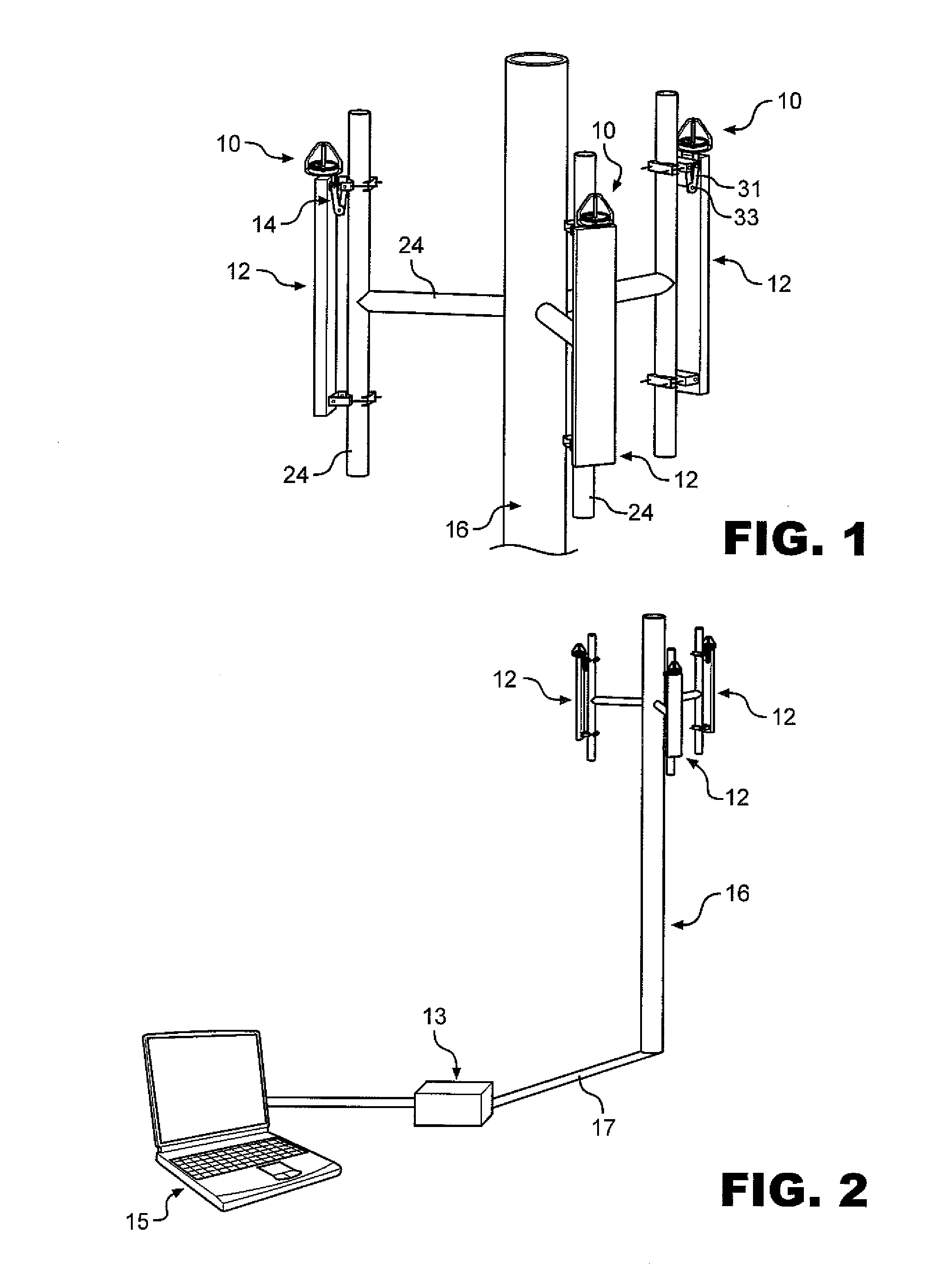
[0023]This invention can be configured in several ways depending on the deployment environment. The basic system as shown in FIG. 1 consists of sensors 10 which mount to antennas 12 to be aligned plus a central data collection and processing unit 13, see FIG. 2. Each sensor 10 is mounted to an aligned directional antenna 12, with a known geometric relationship to the directional characteristic of the antenna. This can be a single or multiple segment antenna, as long as there is a common structure that can be used to define alignment of all the segments.

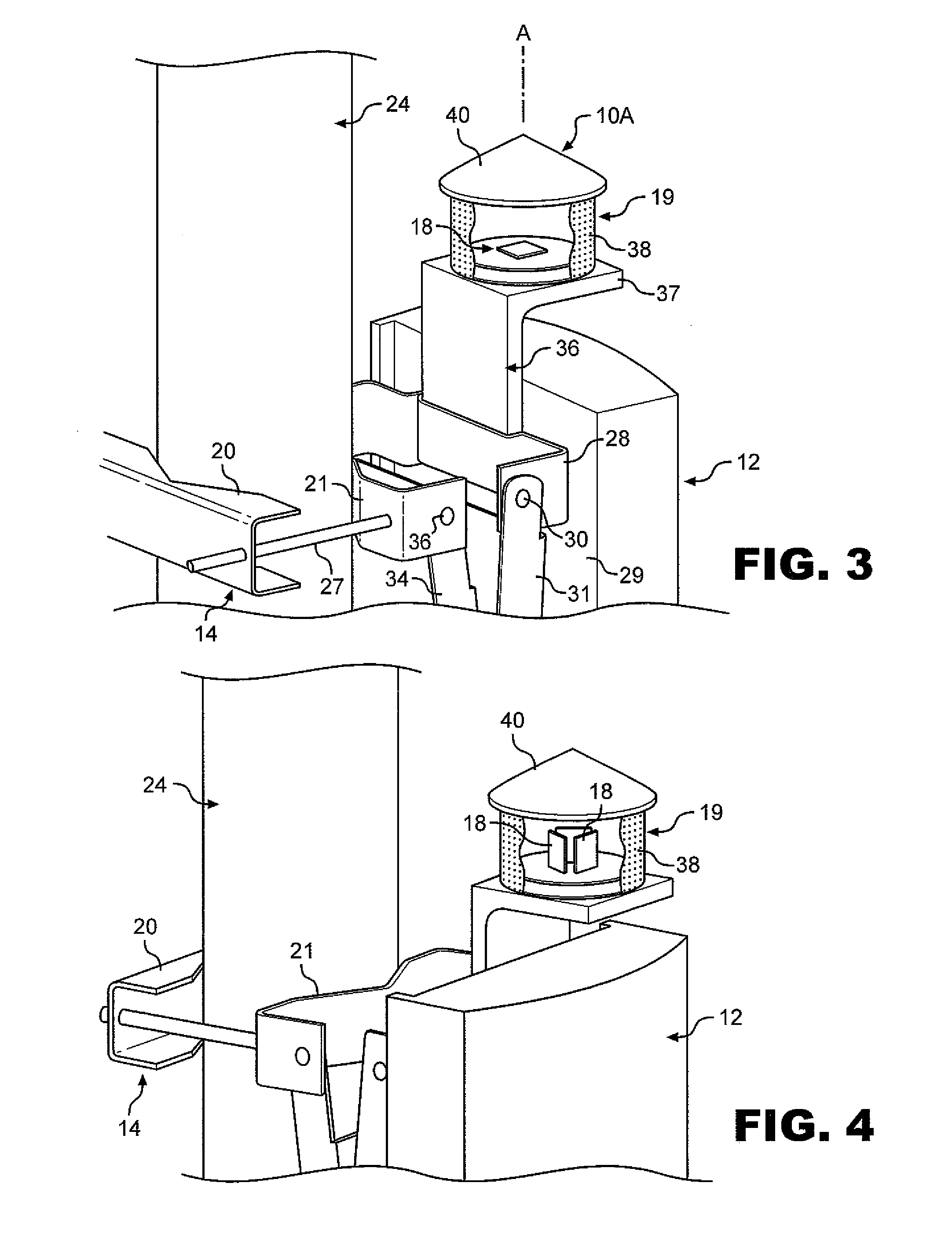
[0024]Antennas are typically mounted on some type of adjustable bracket 14, see FIGS. 3, 4 and 8 allowing adjustment in azimuth or heading and downward tilt angle, the angle below horizontal along the antenna's center of energy heading direction. The antennas are also mounted on a tall pole 16 or tower, or on a building or billboard (not shown) overlooking a coverage area. In the embodiment shown, a plurality of antennas are shown mou...


PUM


Abstract

Alignment monitoring systems for directional and omni-directional antennas that are mounted to the antennas and which include solar sensors that are mounted with enclosing housings such that solar imaging across the surface of one or more sensing elements is used to determine a current alignment of the antennas in at least in one of headings, or azimuths of the antennas, or tilt angles thereof relative to a horizontal plane, and wherein signals generated by the sensing elements are communicated to data processing units.

Description

BACKGROUND OF THE INVENTION[0001]1. Field of the Invention[0002]The present invention relates to the field of directional alignment and alignment monitoring systems for directional and planar pattern omni-directional antennas of all types and particularly to those used in communications. Alignment of directional antennas is important in competitive industries with customers expecting uninterrupted cellular phone service and other communication and data services.[0003]2. Description of the Related Art[0004]Several types of metrological equipment are currently used to align directional antennas. These include conventional construction tools such as levels and transits plus location aides positioned at a distance from the antennas at known headings or locations, determined by such devices including compasses and surveying equipment or satellite global positioning systems (GPS), which can be used to site the antennas using lasers, transits and other optical equipment available to a grou...

Claims


Application Information

Patent Timeline
IPC IPC(8): H01Q1/00
CPCH01Q1/1242H01Q21/29H01Q3/02
Inventor AUSTIN, ROBERT WAYNEMERCIER, GREGORY A.WEDDENDORF, BRUCE
Owner SUNSIGHT HLDG
Why Eureka
Try Eureka