
Exposure apparatus, maintenance method, exposure method, and method for producing device

a technology of exposure apparatus and maintenance method, which is applied in the direction of printing, cleaning using liquids, instruments, etc., can solve the problems of the inability to form an immersion area, so as to suppress the degradation of exposure accuracy and/or measurement accuracy, suppress the lowering of the operation rate of the exposure apparatus, and enhance productivity

Active Publication Date: 2008-01-17
NIKON CORP
View PDF30 Cites 20 Cited by
  • Summary
  • Abstract
  • Description
  • Claims
  • Application Information

AI Technical Summary

Benefits of technology

[0004] In the liquid immersion exposure apparatus, when there arises a problem or inconvenience such that a liquid immersion member, which makes contact with the liquid in the liquid immersion area, is polluted and / or the like, there is a possibility that the liquid immersion area cannot be formed in a desired state due to the problem, resulting in the degradation of the exposure accuracy and / or the measurement accuracy. To address this situation, it is conceivable to make the operator access the liquid immersion member in which the problem has occurred so that the operator performs maintenance operation and / or exchange operation. However, the operation rate of the exposure apparatus is lowered when the operation of the exposure apparatus is paused to perform the maintenance and / or exchange operation for the liquid immersion member.
[0005] An object of the present invention is to provide an exposure apparatus, a maintenance method, an exposure method and a device-producing method with which it is possible to suppress the lowering of the operation rate and / or to suppress the degradation of the exposure accuracy and the like due to the problem or failure in the liquid immersion member.

Problems solved by technology

In the liquid immersion exposure apparatus, when there arises a problem or inconvenience such that a liquid immersion member, which makes contact with the liquid in the liquid immersion area, is polluted and / or the like, there is a possibility that the liquid immersion area cannot be formed in a desired state due to the problem, resulting in the degradation of the exposure accuracy and / or the measurement accuracy.

Method used


Image

  • Exposure apparatus, maintenance method, exposure method, and method for producing device
  • Exposure apparatus, maintenance method, exposure method, and method for producing device
  • Exposure apparatus, maintenance method, exposure method, and method for producing device

Examples


first embodiment

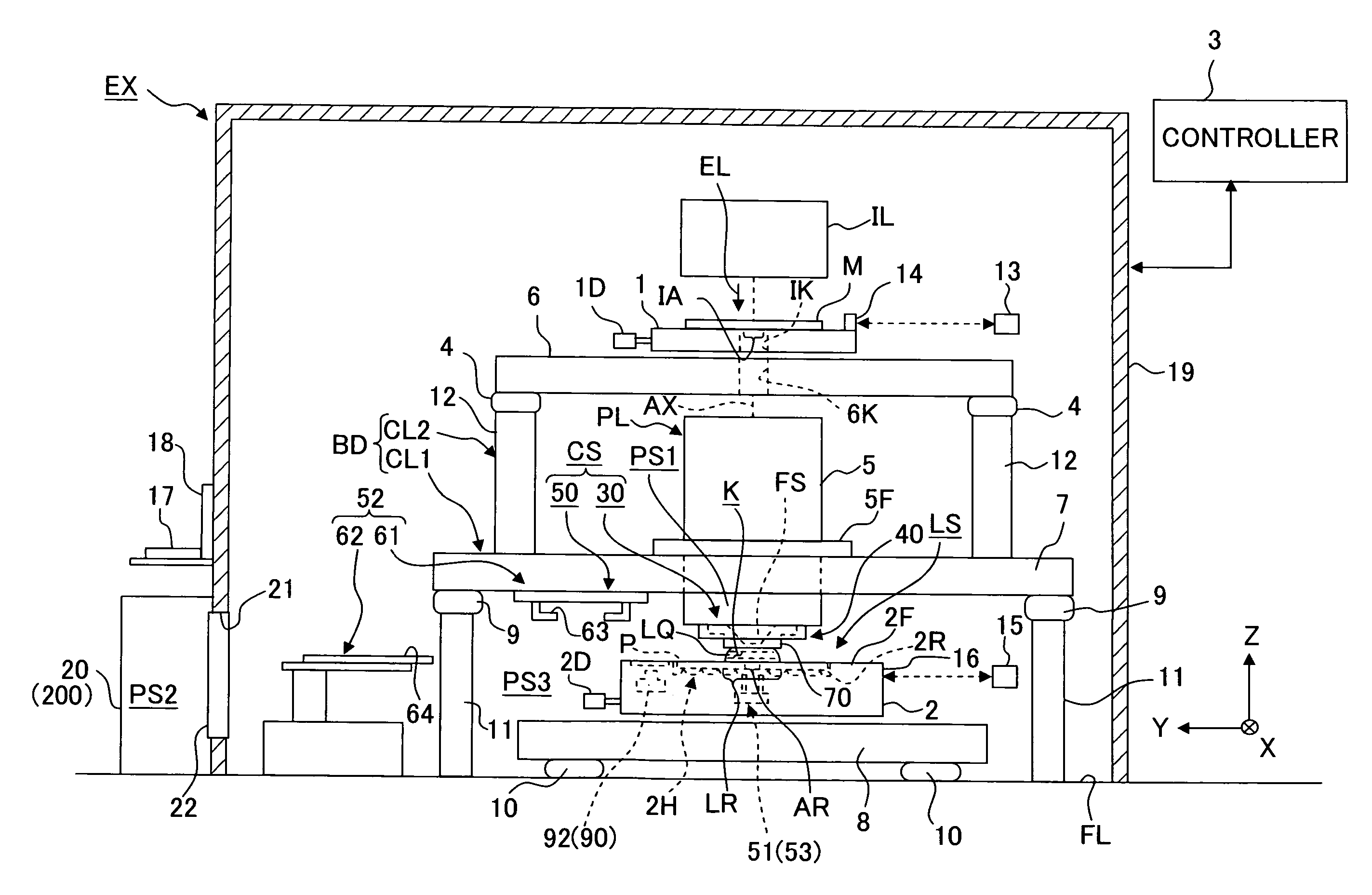
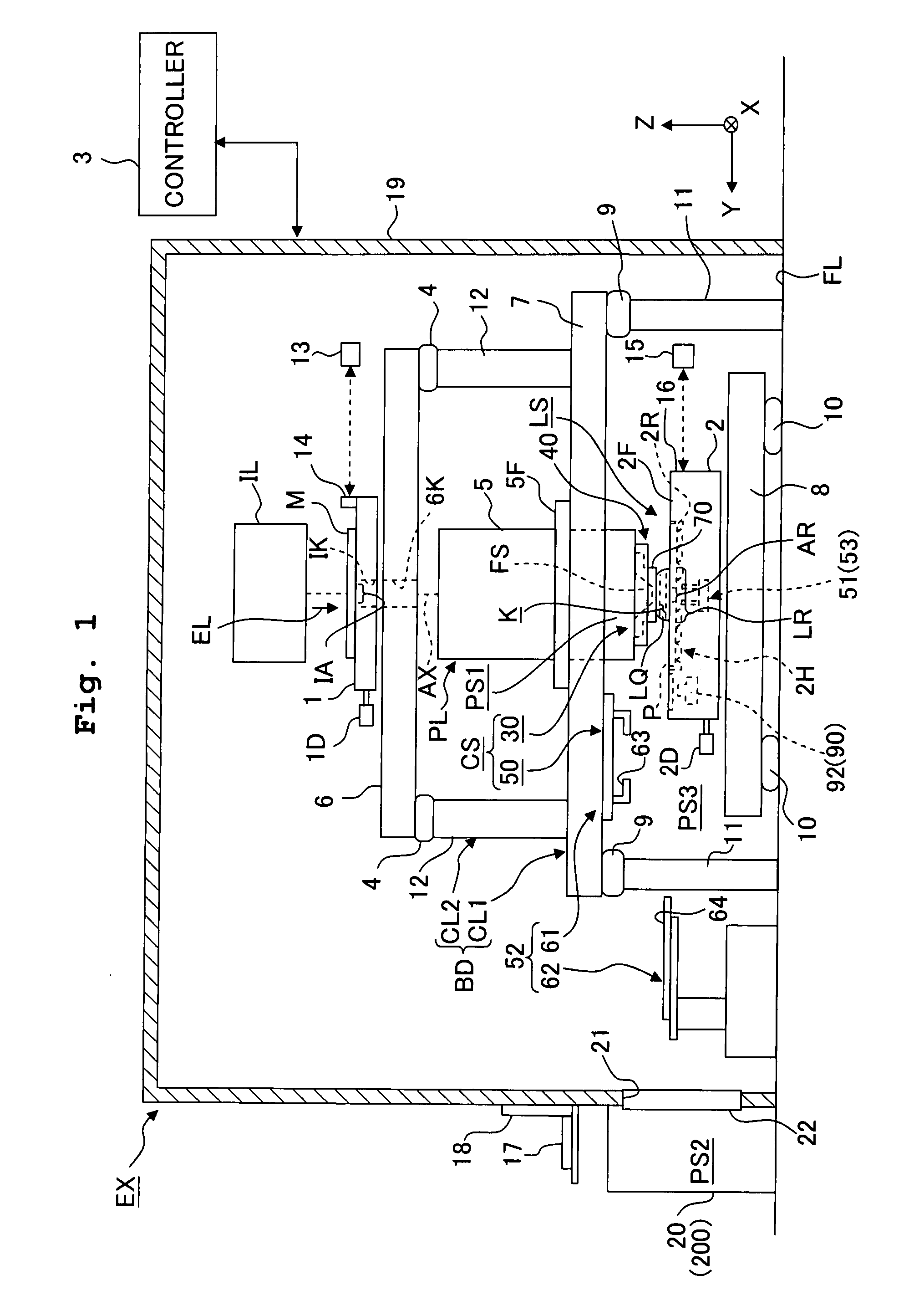
[0044] An explanation will be given about the first embodiment. FIG. 1 is a schematic arrangement view of an exposure apparatus EX according to the first embodiment. Referring to FIG. 1, the exposure apparatus EX includes a mask stage 1 which is movable while holding a mask M thereto; a substrate stage 2 which is movable while holding a substrate P thereto; an illumination optical system IL which illuminates, with an exposure light EL, a pattern of the mask M; a projection optical system PL which projects, onto the substrate P, an image of the pattern of the mask M illuminated with the exposure light EL; and a controller 3 which controls the entire operation of the exposure apparatus EX. Further, the exposure apparatus EX includes an input device 17 which is connected to the controller 3 and via which an operation signal can be inputted to the exposure apparatus EX; and an output device 18 which is connected to the controller 3 and which is capable of outputting an operation state o...

second embodiment

[0138] Next, the second embodiment will be explained with reference to FIG. 18. In the following description, the constitutive parts or components, which are the same as or equivalent to those of the first embodiment described above, are designated by the same reference numerals, any explanation of which will be simplified or omitted.

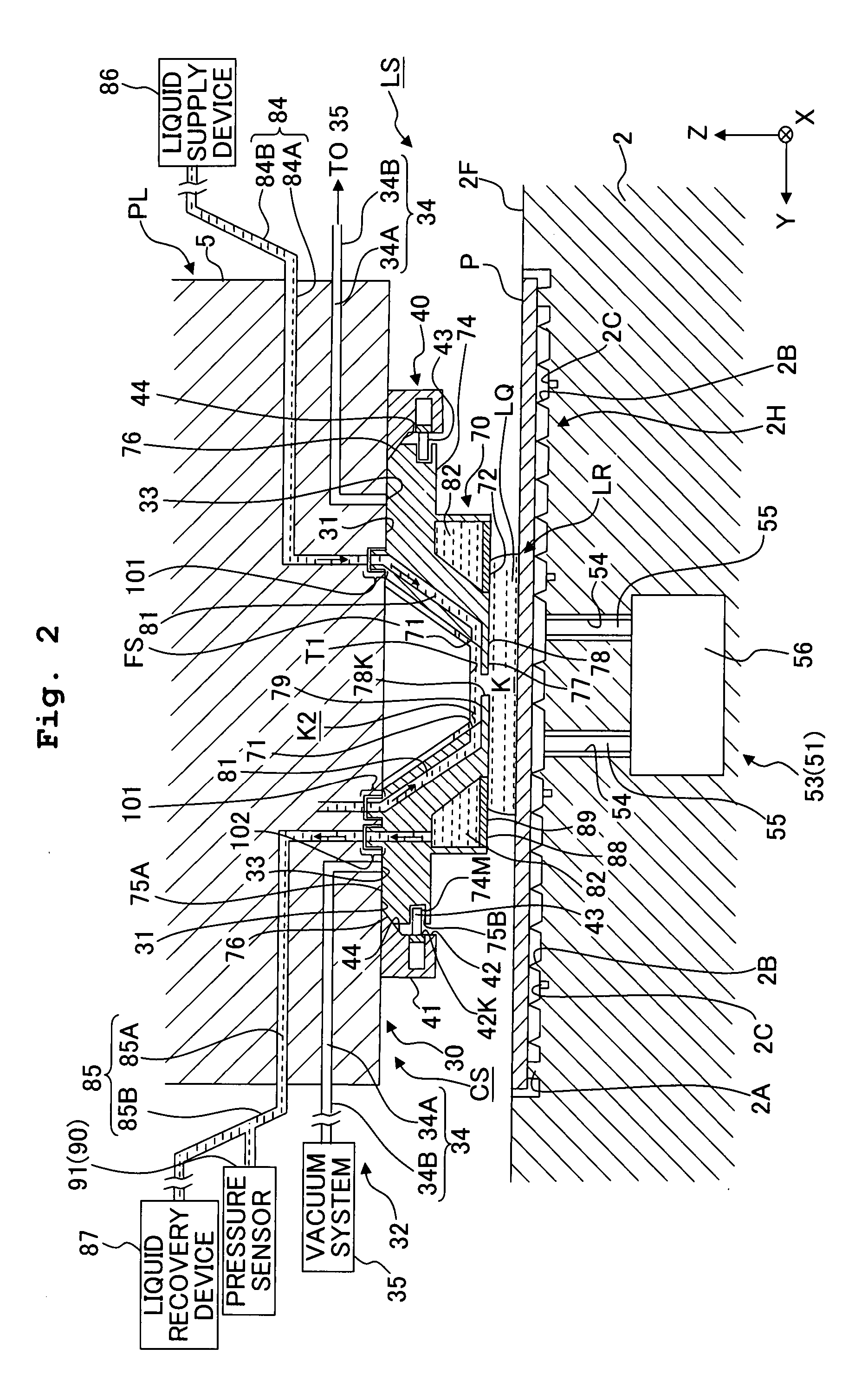
[0139]FIG. 18 is a sectional view showing the main components of the exposure apparatus EX according to the second embodiment. The feature of the second embodiment is that a holding surface 31 of a holding device 30 for holding a liquid immersion member 70 is provided on a support member 110 which is separate or distinct from a barrel 5. The support member 110 is an annular member arranged to surround a final optical element FS, and is provided with the holding surface 31 for holding the liquid immersion member 70 on the lower surface of the support member 110. A suction port 33 of an attraction mechanism 32 is provided on the holding surface 31 of the...

third embodiment

[0143] Next, the third embodiment will be explained with reference to FIG. 19. In the following description, the constitutive parts or components, which are the same as or equivalent to those of the embodiments described above, are designated by the same reference numerals, any explanation of which will be simplified or omitted. In the above-described embodiments, the pin-shaped members 55 of the moving mechanism 53 of the first sub-transport system 51 are arranged in the opening 54 of the substrate holder 2H and are capable of transporting (moving upwardly and downwardly) the substrate P also. In the third embodiment, on the other hand, the pin-shaped members 55 may be provided at a position different from the substrate holder 2H, as schematically shown in FIG. 19. In the example shown in FIG. 19, the pin-shaped members 55 are arranged on the upper surface 2F of the substrate stage 2. In the embodiment, the pin-shaped members which move the substrate P upwardly and downwardly and t...


PUM


Abstract

An exposure apparatus EX includes a liquid immersion system and an exchange system which performs exchange of the liquid immersion member. The exchange system has a holding device which holds the liquid immersion member detachably and a transport device. By using the exchange system, it is possible to suppress the lowering in the working rate due to the cleaning or exchange of the liquid immersion member.

Description

CROSS REFERENCE TO RELATED APPLICATION [0001] The present application claims the benefit of priority from Japanese Patent Application No. 2006-067476 filed on Mar. 13, 2006 and U.S. Provisional Patent Application No. 60 / 785,982 filed on Mar. 27, 2006, the entire disclosures of which are incorporated herein by reference.BACKGROUND OF THE INVENTION FIELD OF THE INVENTION [0002] The present invention relates to an exposure apparatus which exposes a substrate, a maintenance method, an exposure method and a method for producing a device. [0003] As an exposure apparatus used in the photolithography process, there is provided a liquid immersion exposure apparatus which forms a liquid immersion area with a liquid on a substrate and exposes the substrate through the liquid, as disclosed, for example, in International Publication No. 99 / 49504. SUMMARY OF THE INVENTION [0004] In the liquid immersion exposure apparatus, when there arises a problem or inconvenience such that a liquid immersion m...

Claims


Application Information

Patent Timeline
IPC IPC(8): G03B27/54B08B3/00G03C8/00
CPCG03F7/70341G03F7/70975G03F7/7085G03F7/70733G03F7/70908G03F9/7003
Inventor NISHII, YASUFUMI
Owner NIKON CORP
Learn More