Exposure apparatus

a technology of apparatus and substrate, applied in the field of equipment, can solve the problems of deteriorating apparatus functions, measuring by laser interferometer, and and achieve the effect of reducing the positional displacement of the substrate stag

Inactive Publication Date: 2008-01-17
CANON KK
View PDF2 Cites 17 Cited by
  • Summary
  • Abstract
  • Description
  • Claims
  • Application Information

AI Technical Summary

Benefits of technology

[0009]The present invention has been made in view of such problems and it allows the positional displacement of a substrate stage to be reduced in an exposure apparatus in that a plurality of the substrate stages move between a plurality of stations.

Problems solved by technology

The value measured by the laser interferometer may include Abbe errors due to the straightness of the laser light axis and measurement errors due to the surface configuration of the reflection mirror.
These measurement errors result in the position measurement errors of the wafer stage, thus deteriorating apparatus functions.
Thus, if the correction factor is employed, which has been uniquely established for the position measurement errors of the wafer stage in a case of one wafer stage along with one station, the residual correction error is generated, causing the positional displacement of the wafer stage.
Consequently, if the position is displaced along XY-directions, overlapping errors are generated, if along Z-direction, focus errors are generated.

Method used


Image

  • Exposure apparatus
  • Exposure apparatus
  • Exposure apparatus

Examples


Embodiment Construction

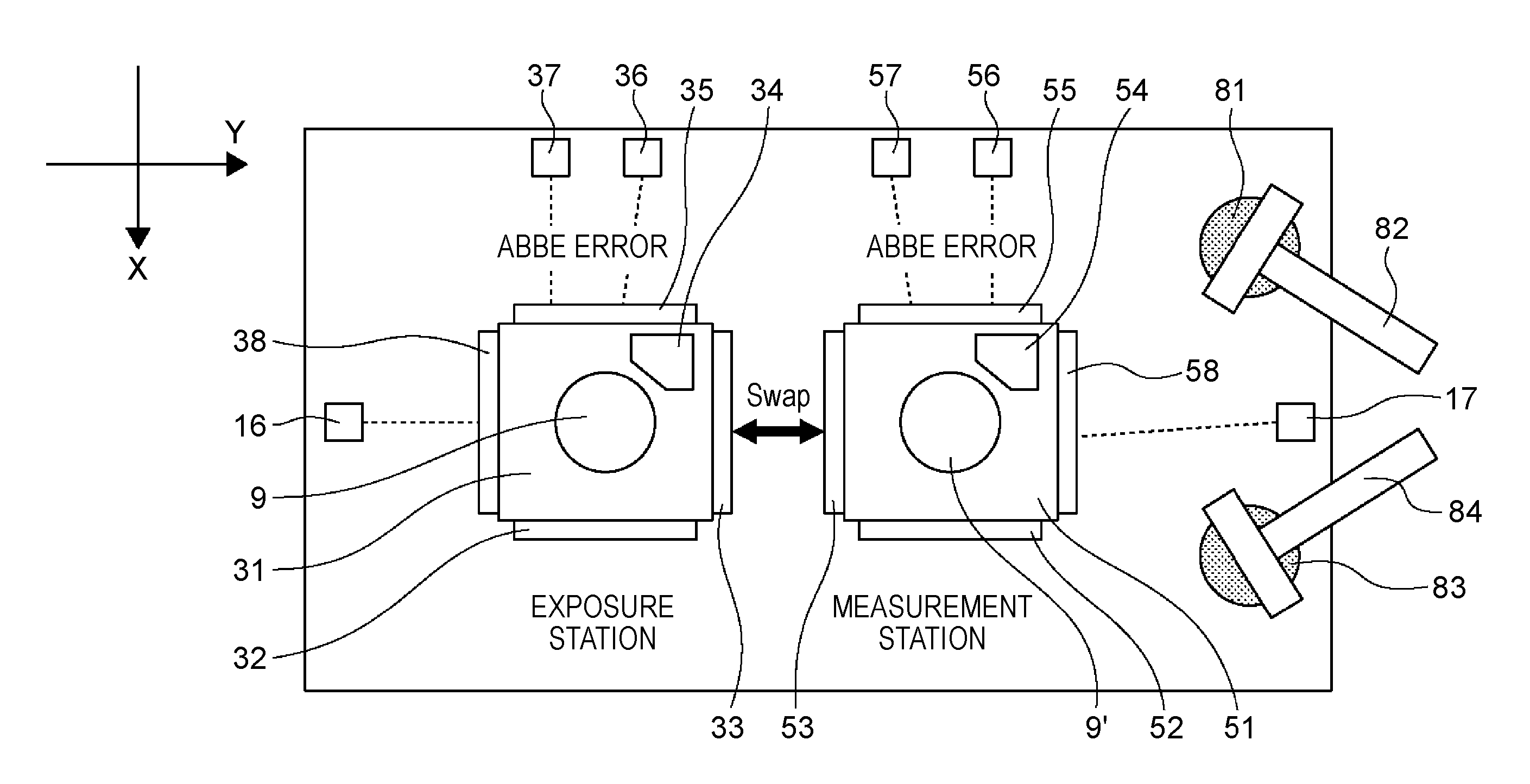
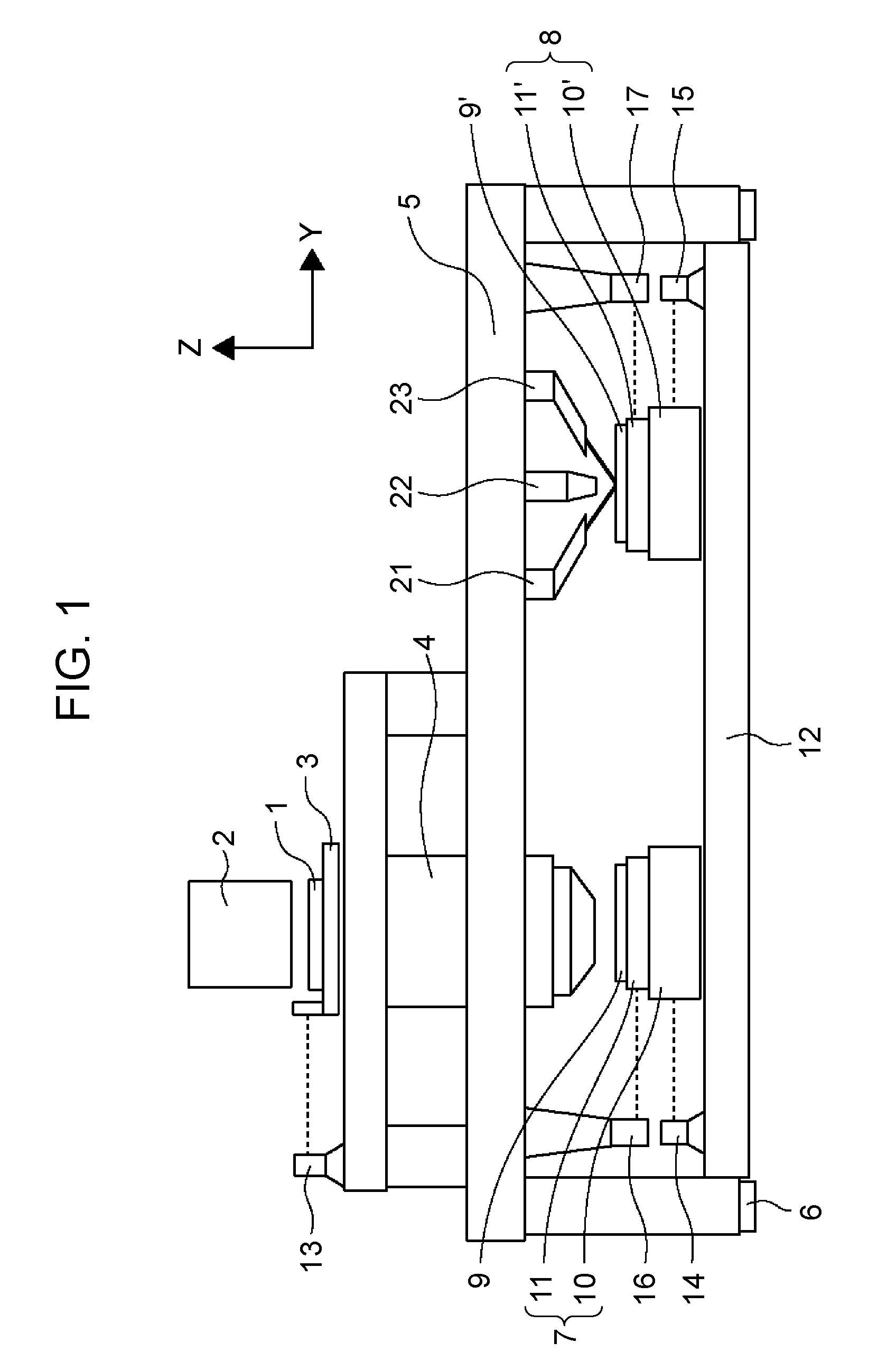
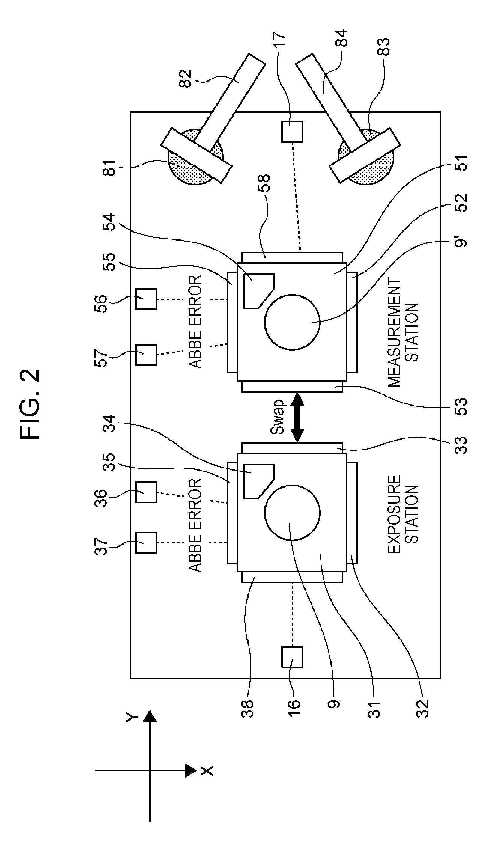
[0022]FIG. 1 is a schematic front view of a twin-stage exposure apparatus according to a preferred embodiment of the present invention. A reticle 1 is held by a reticle stage 3 movable in Y-direction and is illuminated with an illumination unit 2. A pattern formed on the reticle 1 is projected onto a wafer (substrate) 9 by a projection lens (projection optical system) 4 supported to a lens barrel support body 5. An active mount 6 supports the lens barrel support body 5 for suppressing vibration as well as isolating the vibration from the floor for an apparatus body (the lens barrel support body).

[0023]A stage base 12 supports a first wafer stage (a first substrate stage) 7 and a second wafer stage (a second substrate stage) 8. First, the first wafer stage 7 will be described. The first wafer stage 7 includes a coarse-motion stage 10 movable in XY-directions and a fine-motion stage 11 movable relative to the coarse-motion stage 10 in 6-axial directions X, Y, Z, ωX, ωY, and ωZ by an a...


PUM


Abstract

In an exposure apparatus having a plurality of substrate stages moving between a plurality of stations, errors due to the combination of the stage and a position measuring unit, such as Abbe error and errors due to the surface configuration of a reflection mirror, are precisely corrected to reduce the position error of the substrate stage. The exposure apparatus includes a control device having a storage unit and a correction unit. The storage unit stores the correction information established every combination of the plurality of substrate stages and a plurality of position measuring units, and the correction unit corrects the result measured by the plurality of position measuring units on the basis of the correction information corresponding to the combination of the substrate stages and the position measuring units among pieces of correction information stored in the storage unit.

Description

BACKGROUND OF THE INVENTION[0001]1. Field of the Invention[0002]The present invention relates to an exposure apparatus having a plurality of substrate stages.[0003]2. Description of the Related Art[0004]In a photo-lithographic process for manufacturing semiconductor devices, an exposure apparatus is incorporated for transferring a reticle fine pattern onto a wafer having a photosensitive material coated thereon. An exposure apparatus in the related art includes one wafer stage so that the processes of carrying-in the wafer, alignment measurement, exposure, and carrying-out the wafer are performed in series.[0005]However, for further improving a throughput, a twin-stage exposure apparatus including two wafer stages has been recently adopted. The twin-stage exposure apparatus includes two stations of measurement and exposure. Such a twin-stage exposure apparatus is disclosed in Japanese Patent Laid-Open No. 2000-323404, for example.[0006]The position measurement of the wafer stage rel...

Claims


Application Information

Patent Timeline
Patent Type & Authority Applications(United States)
IPC IPC(8): G01B11/00
CPCG03F7/70775G03F7/70733
Inventor AKIMOTO, SATOSHI
Owner CANON KK
Why Eureka
Try Eureka