Approach for Reducing Injector Fouling and Thermal Degradation for a Multi-Injector Engine System

Active Publication Date: 2008-01-24
FORD GLOBAL TECH LLC +1
View PDF99 Cites 31 Cited by
  • Summary
  • Abstract
  • Description
  • Claims
  • Application Information

AI Technical Summary

Benefits of technology

[0003]Engines have been described utilizing multiple injector locations with different fuel types. One example is described in the papers titled “Calculations of Knock Suppression in Highly Turbocharged Gasoline/Ethanol Engines Using Direct Ethanol Injection” and “Direct Injection Ethanol Boosted Gasoline Engine: Biofuel Leveraging for Cost Effective Reduction of Oil Dependence and CO2 Emissions” by Heywood et al. Specifically, the Heywood et al. papers describes directly injecting ethanol to improve charge cooling effects, while relying on port injected gasoline for providing the majority of combusted fuel over a drive cycle.
[0004]The inventors herein have recognized that under some conditions, such as where one of the injectors is not continuously injecting a fuel or other substance, subsequent operation of the injector may become degraded where injector fouling occurs. As one example, a direct injector may become fouled where soot or other products of combustion form on or around the injector nozzle, thereby reducing injector performance.
[0005]The inventors herein have also recognized that the temperature of the injector may increase during periods where the injector is not performing an injection since the injection of a substance can cool the injector and/or stagnation of the substance downstream of the injector may remove less heat from injector. If the period between injection events becomes too great, the injector can exceed a temperature threshold at which injector degradation and/or failure occurs. Further, at high injector temperatures, the substance passing through the injecto

Problems solved by technology

As one example, a direct injector may become fouled where soot or other products of combustion form on or around the injector nozzle, thereby reducing injector performance.
If the period between injection events becomes too great, the injector can exceed a temperature threshold at which injector degradation and/or failure occurs.
Further, at hig

Method used


Image

  • Approach for Reducing Injector Fouling and Thermal Degradation for a Multi-Injector Engine System
  • Approach for Reducing Injector Fouling and Thermal Degradation for a Multi-Injector Engine System
  • Approach for Reducing Injector Fouling and Thermal Degradation for a Multi-Injector Engine System

Examples


Example

[0016]Gasoline engines, particularly those with a boosting device, may employ a variable direct injection of a knock suppressing fuel such as an alcohol or alcohol blend to provide improved performance. As one prophetic example, a high compression ratio, boosted engine configured with selective and variable ethanol direct injection in addition to gasoline injection may achieve a 20%-30% increase in efficiency over a naturally aspirated spark ignition engine when delivering the same torque and power. The directly injected ethanol can provide a large knock suppression effect due in part to the evaporative cooling of the fuel / air charge within the cylinder of the engine. This improvement in efficiency can enable the engine to be substantially downsized and / or operate at a higher compression ratio while providing a similar level of performance.

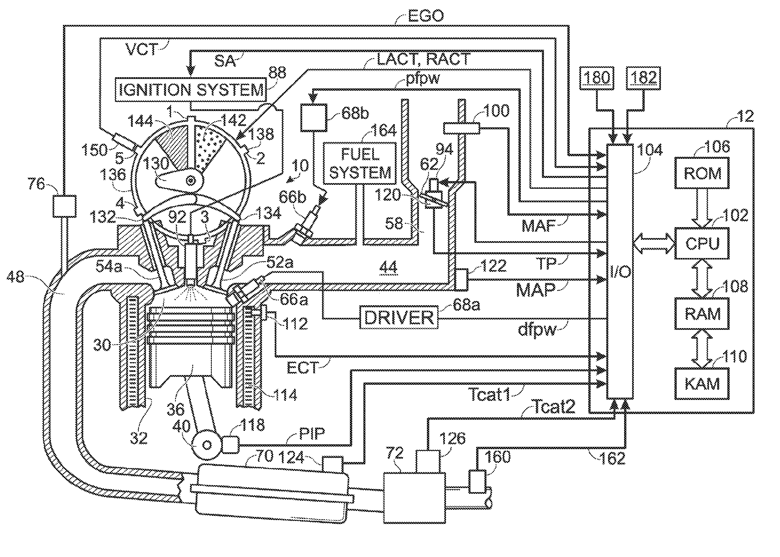
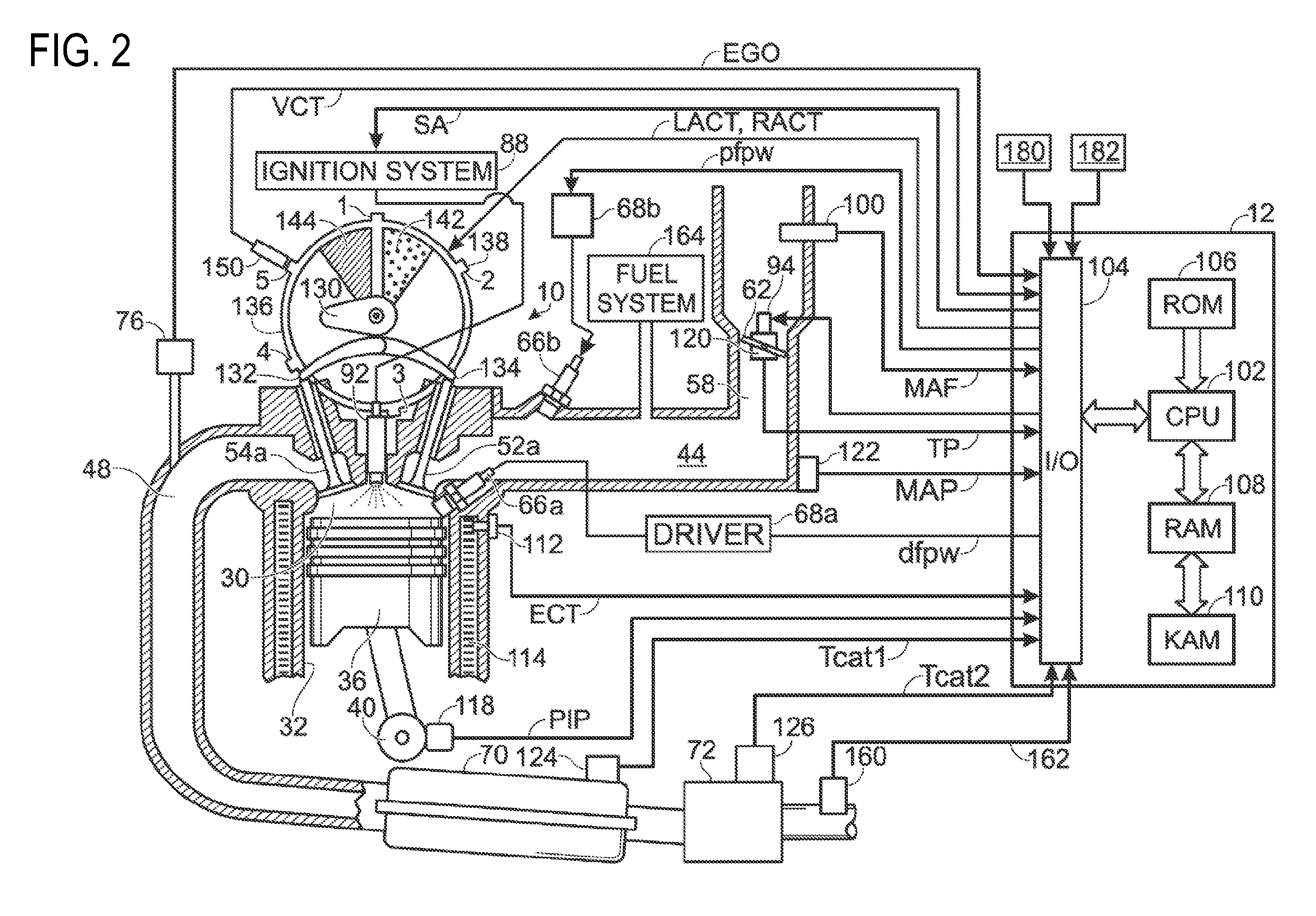
[0017]FIG. 1 is a schematic illustration of an example engine 10 receiving delivery of a plurality of substances (1, 2, . . . , N) as indicated b...


PUM


Abstract

As one embodiment, a method of operating an engine of a vehicle is provided wherein the engine has a variable engine output. The method comprises during a first engine output, delivering a first fuel to at least a cylinder of the engine via a first injector and directly injecting a second fuel directly into said cylinder via a second injector; and during a second engine output lower than said first engine output, delivering said first fuel to said at least a cylinder of the engine via said first injector and directly injecting at least a purging substance via said second injector based on an idle period since a previous injection by said second injector.

Description

[0001]The present application claims priority to U.S. Provisional Patent Application No. 60 / 832,836, filed Jul. 24, 2006, and entitled “Single Nozzle System for Rapidly Variable Direct Injection of Gasoline and Ethanol Mixtures”, the entire contents of which are incorporated herein by reference.BACKGROUND AND SUMMARY[0002]Engines may use various forms of fuel delivery to provide a desired amount of fuel for combustion in each cylinder. One type of fuel delivery uses a port injector to deliver fuel to respective cylinders. Still another type of fuel delivery uses a direct injector for each cylinder.[0003]Engines have been described utilizing multiple injector locations with different fuel types. One example is described in the papers titled “Calculations of Knock Suppression in Highly Turbocharged Gasoline / Ethanol Engines Using Direct Ethanol Injection” and “Direct Injection Ethanol Boosted Gasoline Engine: Biofuel Leveraging for Cost Effective Reduction of Oil Dependence and CO2 Emi...

Claims


Application Information

Patent Timeline
IPC IPC(8): F02D41/30
CPCF02D19/12F02D41/0025F02P5/1527Y02T10/36Y02T10/46F02D19/084F02D19/0621F02D19/0623F02D19/0665F02D19/0689F02D19/0692F02D19/061Y02T10/30Y02T10/40
Inventor STEIN, ROBERT A.BROMBERG, LESLIEBLUMBERG, PAUL N.COHN, DANIEL R.HEYWOOD, JOHN B.
Owner FORD GLOBAL TECH LLC
Why Eureka
Try Eureka