
Medicament dispenser

a technology of medicine dispensers and dispensers, which is applied in the field of medicine dispensers, can solve the problems of false readings, triggering of sensors, and false readings being registered on the dose counter, etc., and achieve the effects of reducing power dissipation in resistive components, reducing current, and low resistan

Inactive Publication Date: 2008-01-24
GLAXO GRP LTD
View PDF12 Cites 46 Cited by
  • Summary
  • Abstract
  • Description
  • Claims
  • Application Information

AI Technical Summary

Benefits of technology

The present invention provides a medicament dispenser with an electronic dose counter that includes a housing with an outlet, a medicament container locatable within the housing, and an electronic dose counter associated with the outlet. The dose counter includes a first sensor that directly detects a medicament release through the outlet. The first sensor may be an emitter that emits infrared radiation and a detector that detects the radiation. The detector may be a photodiode, phototransistor, light-dependent resistor, or bolometer. The emitter may be a light emitting diode, laser, incandescent lamp, or other suitable emitter. The detector may be a photodiode, phototransistor, light-dependent resistor, or bolometer. The detector may have a filter to select a specific wavelength or range of wavelengths. The interference caused by the medicament release may result in either an increase or decrease in the amount of radiation detected by the detector. The interference may be caused by absorption, scattering, refraction, or diffraction of the radiation. The dose counter can quantify the concentration of the medicament in the medicament container by measuring the radiation at more than one wavelength.

Problems solved by technology

One problem associated with both mechanical and electrical dose counters is that they may, on occasions, give false readings.
A general problem encountered with dose counters in the art, such as those described above, is that they are dependent upon sensors which do not directly detect the medicament release from the dispenser.
This indirect method of sensing medicament release can lead to false readings being registered on the dose counter, if for example the sensor is activated without release of medicament.
Accidental activation or triggering of the sensor may, for example, result from partial movement of the container or from interference with light received by the sensor.
Similarly, a blockage or only partial release of the drug from either an MDI or dry powder inhaler would lead to a false reading registering on the dose counter.

Method used


Image

  • Medicament dispenser
  • Medicament dispenser
  • Medicament dispenser

Examples


Embodiment Construction

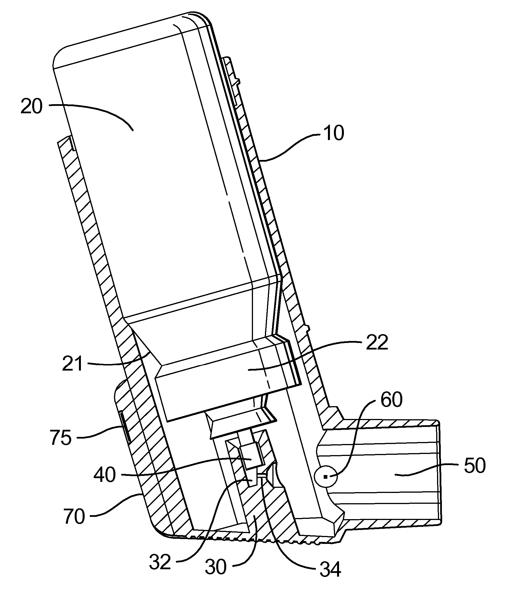
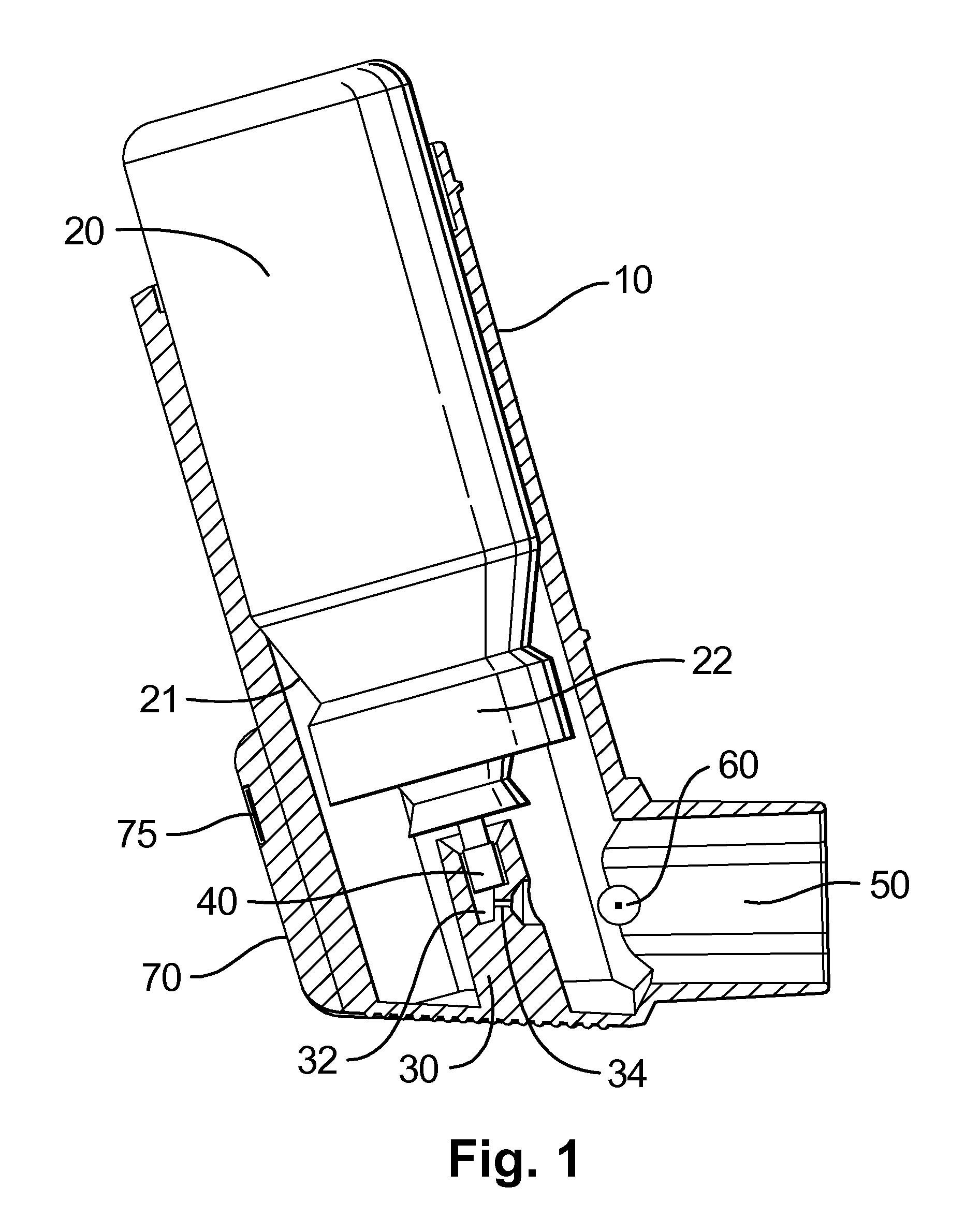
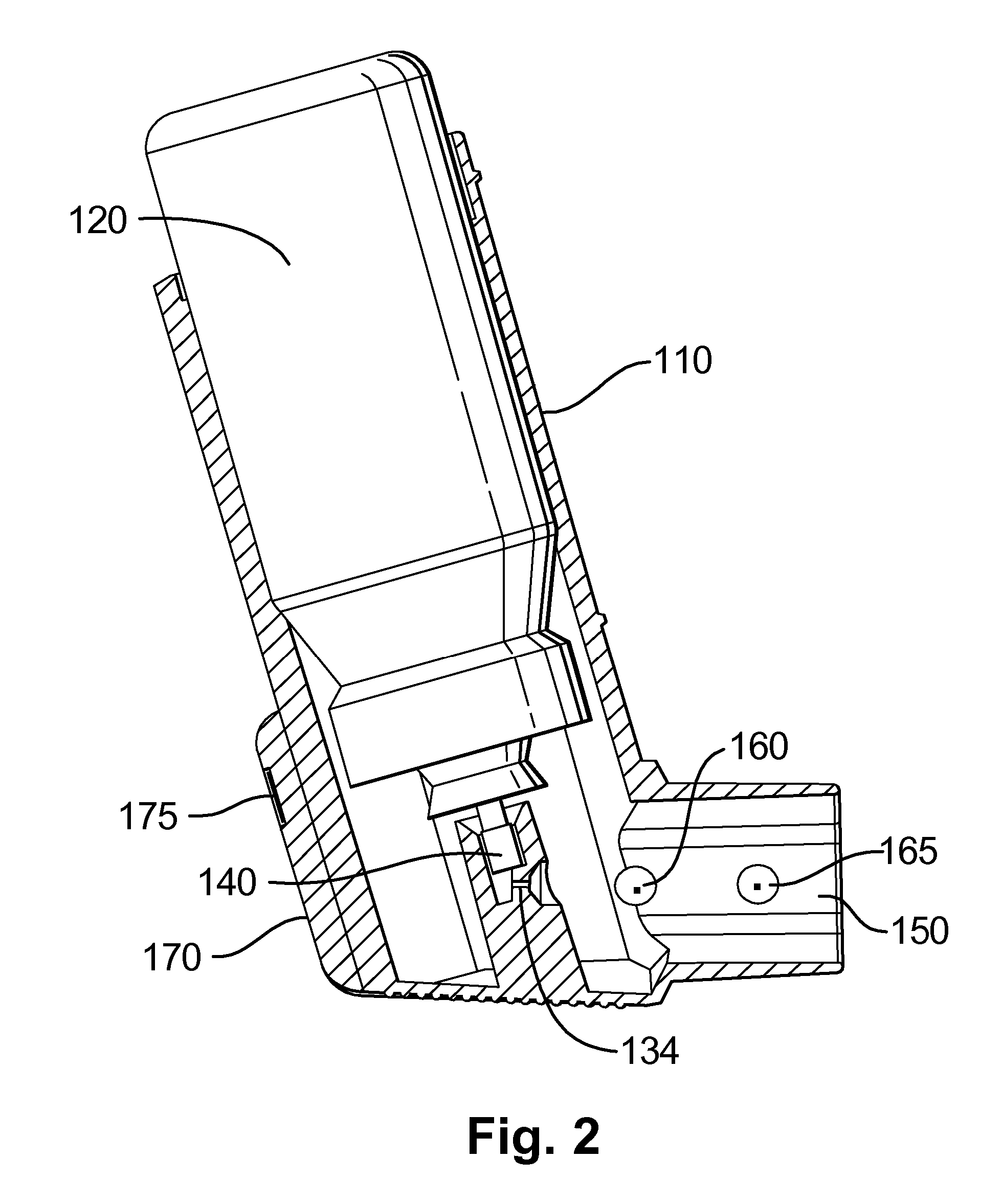
[0080] For the sake of brevity, each drawing depicts a sensor comprising an emitter / detector pair which emit and are responsive to infra red radiation. It should be understood that other forms of sensors, detailed herein, could equally be described in the drawings and used in the present invention. Furthermore, the drawings could equally apply to a sensor comprising only of a detector and lacking the corresponding emitter.

[0081] As shown in the cross-sectional perspective of FIG. 1, the aerosol canister 20 is located in the housing 10 so that one end protrudes from its open top, the canister being positioned such that the neck 21 and valve ferrule 22 are enclosed within housing 10. Spacer ribs (not shown) may be provided inside the housing to hold the external surface of the canister 20 spaced from the internal surface of the housing 10. A support 30 is provided at the lower end of the housing 10 and has a passage 32 in which the valve stem 40 of the aerosol canister 20 can be loca...


PUM


Abstract

A medicament dispenser comprising: (i) a housing having an outlet; (ii) a medicament container locatable within said housing; (iii) an electronic dose counter associated with said outlet, wherein said dose counter comprises a first sensor for directly detecting a medicament release dispensible from said medicament container through said outlet is disclosed.

Description

CROSS-REFERENCE TO RELATED APPLICATIONS [0001] This patent application is a continuation application of pending U.S. patent application Ser. No. 10 / 415279 filed on Mar. 1, 2004, 35 USC 371 United States National Phase Application of International Patent Application Serial No. PCT / EP01 / 12108, filed 19 Oct. 2001, which claims priority from GB 0026646.0 filed on 31 Oct. 2000 in the United Kingdom.FIELD OF THE INVENTION [0002] This invention relates to a medicament dispenser, particularly dry powder and metered dose inhalation devices, which have dose counters attached thereto. In particular, the invention relates to sensors used with dose counters to detect and validate release of medicament from the dispenser. BACKGROUND OF THE INVENTION [0003] Medicaments for treating respiratory disorders are frequently administered as dry powder formulations through the mouth and nose. Dry powder inhalation devices, or inhalers, are used in the administration of these drugs, inhalation by the patie...

Claims


Application Information

Patent Timeline
Patent Type & Authority Applications(United States)
IPC IPC(8): A61M11/08A61M15/00A61M13/00
CPCA61M15/009A61M15/008A61M2205/52A61M2205/3306A61M2205/8212
Inventor JONES, ANTHONY PATRICKHORTON, ANDREW PAULHARTLEY, RICHARD WILLIAM
Owner GLAXO GRP LTD
Learn More