
Sidewall temperature control systems and methods and improved electrolysis cells relating to same

Inactive Publication Date: 2008-01-24
ARCONIC INC
View PDF12 Cites 5 Cited by
  • Summary
  • Abstract
  • Description
  • Claims
  • Application Information

AI Technical Summary

Benefits of technology

[0009]In view of the foregoing, a broad objective of the present invention is to provide apparatus, systems and methods adapted to maintain the profile of the ledge that forms during operations of an electrolytic cell. In addressing this objective, the present inventors have recognized that controlled cooling of various portions of the sidewalls of an electrolytic cell will facilitate the maintenance of the ledge profile. The present inventors have also recognized that dynamic and selective cooling of differing portions of the sidewall (e.g., cooling certain portions of the sidewall at a different rate than other portions of the sidewall) may facilitate the maintenance of the desired ledge profile.
[0010]More particularly, the present inventors have recognized that a plurality of fluid discharge devices may be utilized in conjunction with a sidewall and outer shell arrangement to selectively provide coolant to the sidewall. The present inventors have recognized that such an arrangement allows for the selective cooling of various portions of the sidewall, which facilitates ledge maintenance and profile.
[0011]In one aspect of the invention, an electrolysis cell is provided, the electrolysis cell having an outer shell, an internal sidewall proximal the outer shell and being spaced therefrom, thereby defining a gap between the sidewall and the outer shell, and a plurality of fluid discharge devices interconnected about the outer shell. The fluid discharge devices are generally adapted to discharge coolant towards at least a portion of the sidewall and at least one of the fluid discharge devices extends from the outer shell towards the sidewall. In one approach, at least one of the plurality of fluid discharge devices extends at least partially into the gap between the sidewall and the outer shell. In a particular embodiment, at least one of the fluid discharge devices is configured to discharge coolant at a selected trajectory, such as at a trajectory that is transverse to the inlet trajectory. In this regard, one or more of the plurality of fluid discharge devices may comprise a fingerlike shape. The fluid discharge devices may also be moveable to change the discharge trajectory of the coolant. In one embodiment, at least one of the fluid discharge devices is rotatable about an axis (e.g., a center axis) to facilitate the selected discharge trajectory.
[0014]As noted, the electrolysis cell includes an outer shell and a sidewall. The outer shell and / or the sidewall may comprise tailored layers to facilitate more efficient operation of the electrolysis cell. For example, the outer shell may include one or more of a containment layer and an insulative layer. The containment layer is generally the outermost layer of the outer shell. The containment layer may be interconnected to the insulative layer and the containment layer may comprise a material adapted to contain molten materials. The insulative layer is generally disposed proximal the gap between the outer shell and sidewall, and thus the insulative layer restricts thermal communication between the sidewall and the outer shell. Hence, a substantial temperature difference between the sidewall and outer shell may be witnessed. Additionally, the exterior surface temperature of the outer shell may be significantly reduced relative to traditional electrolysis cells, which may provide a safer and more environmentally friendly working environment.

Problems solved by technology

If the ledge is too thin, the bath may attack the sidewalls of the tank, which may lead to failure of the cell.
If the ledge is too thick, unstable cell operation may be witnessed.
Natural convection is undesirable in that, for instance, it is not controllable and thus proves difficult to maintain ledge stability, wastes energy and may lead to an unpleasant working environment.
Primarily, many of such approaches are inefficient at maintaining a desired ledge profile, resulting in inefficient cell operation.
Therefore, it is believed that none of the above-described systems have achieved commercial success.

Method used


Image

  • Sidewall temperature control systems and methods and improved electrolysis cells relating to same
  • Sidewall temperature control systems and methods and improved electrolysis cells relating to same
  • Sidewall temperature control systems and methods and improved electrolysis cells relating to same

Examples


Embodiment Construction

[0033]Reference will now be made to the accompanying drawings, which at least assist in illustrating various pertinent features of the present invention.

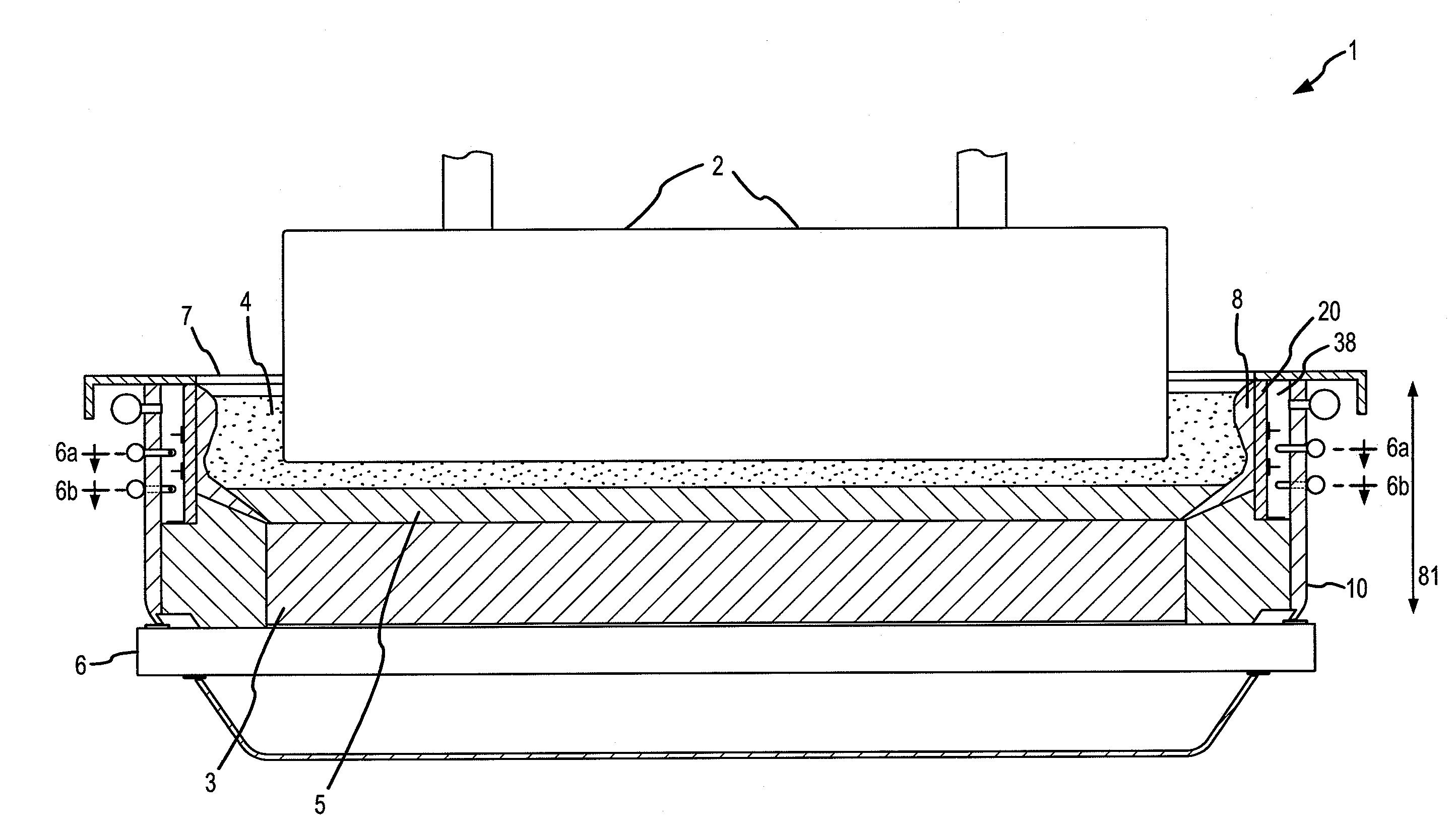
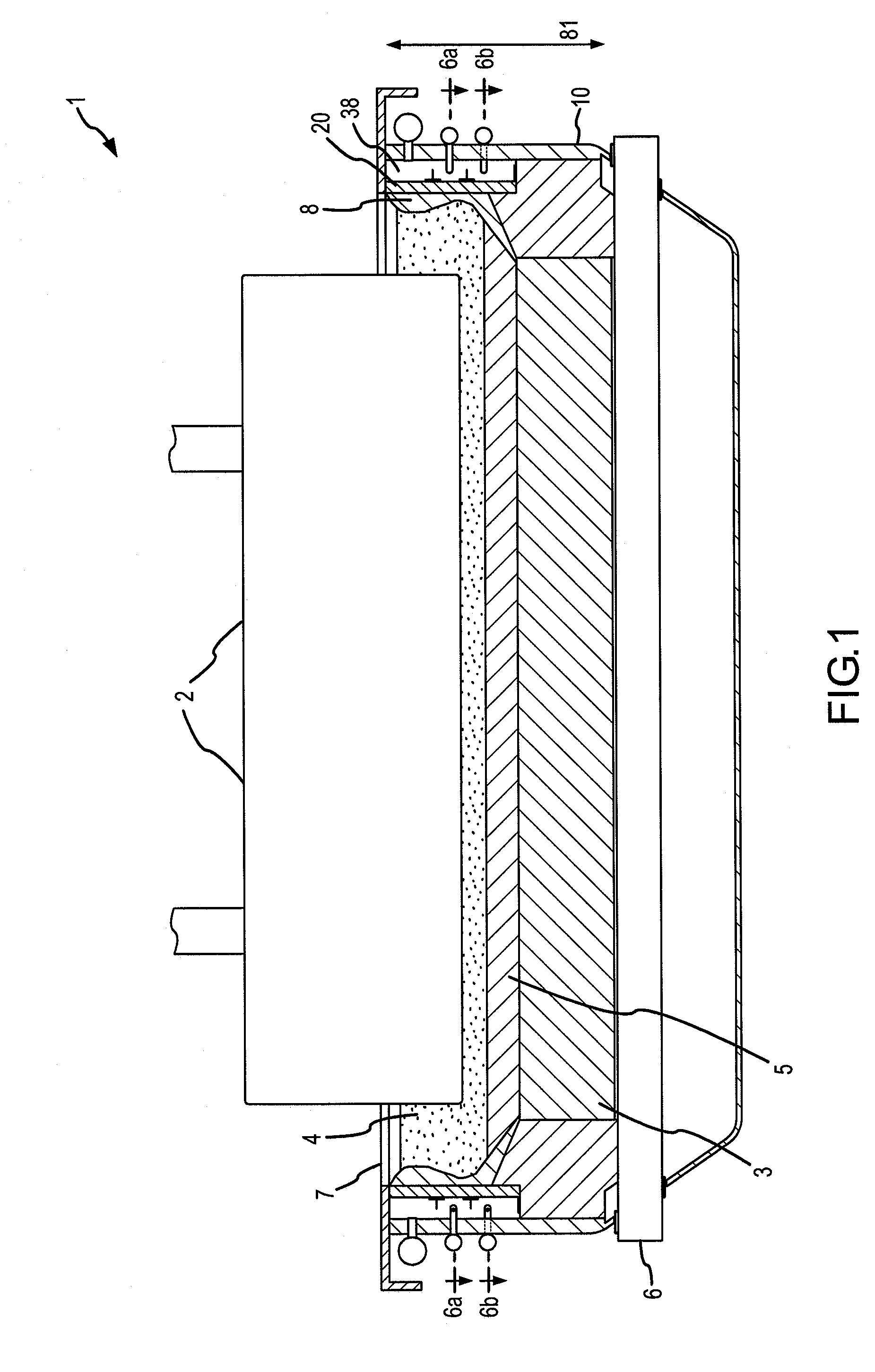
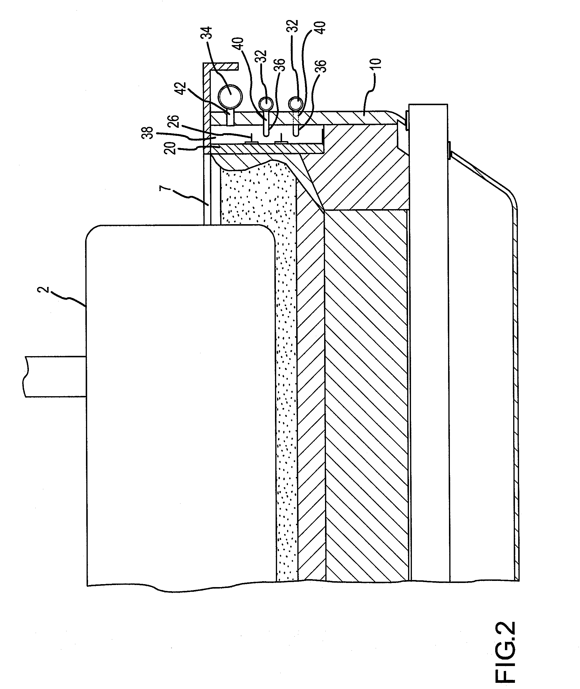
[0034]FIG. 1 illustrates an electrolytic aluminum production cell useful in accordance with the present invention. The electrolytic cell 1 includes an outer shell 10, an anode 2, a cathode 3, a current collector 6 interconnected to the cathode 3, and a top 7. A sidewall 20 is disposed adjacent the outer shell 10 and is spaced therefrom, thereby creating a gap 38 between the outer shell 10 and the sidewall 20. In operation, electric current is passed from the anode 2, through a molten electrolyte bath 4, thereby reducing a metal oxide (e.g., alumina) contained in the bath 4 to a molten metal 5 (e.g., aluminum). A ledge 8 of frozen electrolyte (e.g., cryolite) forms during operation of the cell. The formation of the ledge 8 and the ledge's profile is facilitated via the supply of coolant to the sidewall 20.

[0035]More particularly and ...


PUM

PropertyMeasurementUnit
Temperatureaaaaaaaaaa
Flow rateaaaaaaaaaa
Trajectoryaaaaaaaaaa

Abstract

An electrolysis cell including an outer shell, a sidewall adjacent the outer shell and spaced therefrom, thereby defining a gap between the sidewall and the outer shell, and a plurality of fluid discharge devices interconnected about the outer shell, each of the plurality of fluid discharge devices extending from the outer shell towards the sidewall, wherein each of the plurality of fluid discharge devices is adapted to provide coolant to the sidewall. The plurality of fluid discharge devices may be individually controlled or controlled in sets to provide selective cooling to the sidewall, thereby facilitating ledge maintenance and profile.

Description

CROSS REFERENCE TO RELATED APPLICATION[0001]This application claims priority to U.S. Provisional Application No. 60 / 820,219, filed Jul. 24, 2006, entitled “SIDEWALL TEMPERATURE CONTROL SYSTEMS AND METHODS AND IMPROVED ELECTROLYSIS CELLS RELATING TO SAME”, which is incorporated herein by reference in its entirety.FIELD OF THE INVENTION[0002]The present invention relates to sidewall temperature control systems useful in electrolysis cells and associated methods for controlling the temperature of sidewalls in electrolysis cells. More particularly, the present invention relates to systems and methods for providing controlled flow of one or more coolants to the sidewalls of an electrolysis cell. The present invention also relates to improved electrolysis cells that may be utilized with such systems and methods.BACKGROUND OF THE INVENTION[0003]A number of metals, including aluminum, lead, magnesium, zinc, zirconium, titanium, and silicon, can be produced by electrolytic processes. One exa...

Claims


Application Information

Patent Timeline
IPC IPC(8): H01M10/44
CPCC25C3/085C25C7/005C25C3/20
Inventor LIU, XINGHUABEELER, RICHARDHORNACK, THOMASBURG, JAMESCZEKAJ, STEVEN
Owner ARCONIC INC
Learn More