Slip resistant roof underlayment

a technology of roof and underlayment, applied in the field of underlayment, can solve the problems of creating a slippery surface for workers installing asphalt, conventional underlayments become slippery, etc., and achieve the effects of improving bonding, abrasion resistance and lay flat quality, and increasing shear strength

Active Publication Date: 2008-01-24
KIRSCH RES & DEV
View PDF15 Cites 31 Cited by
  • Summary
  • Abstract
  • Description
  • Claims
  • Application Information

AI Technical Summary

Benefits of technology

[0006]In accordance with a first embodiment of the present invention, a roofing underlayment having a slip resistant surface is provided that comprises a woven scrim made from polypropylene tapes or fibers, a top layer made from a non-woven, spun-bond polypropylene fabric, and a polypropylene coating applied between the scrim and the top layer. The polypropylene coating is impregnated into the weaves of the woven fabric of the scrim, forming a structural bottom layer with increased shear strength, abrasion resistance and lay flat quality. The non-woven top layer is deeply pressed into the coating layer, with the non-woven fibers of the top layer providing a micro-textured surface that exhibits improved traction and a more secure anchoring surface for adhesive foam, as compared to prior art underlayments. Pressing the non-woven top layer into the coating layer, instead of simply using the coating as a glue to bond the non-woven layer to the woven scrim, inhibits the fibers in the non-woven top layer from “pencil rolling” or pulling away from the surface of the roof underlayment.
[0007]This impregnation of the scrim with the polypropylene coating provides improved bonding with the non-woven fabric of the top layer, thereby reducing the chances of delamination of the two layers. Extrusion lamination is used to bond the layers together, creating the roofing underlayment, according to the first embodiment. The top surface of the finished roof underlayment may advantageously be surface treated by passing it under a “corona treater,” which reduces static build-up that may cause production or quality problems, and which provides adhesion for printing as well as proper adhesion of polyurethane foam adhesives to bond with the non-woven surface layer of the roof underlayment.
[0008]In accordance with a second embodiment of the present invention, a roofing underlayment having a slip resistant surface is provided that comprises a scrim woven from polypropylene tapes or fibers, a top layer made from a non-woven spun-bond polypropylene fabric, a first polypropylene coating between the scrim and the top layer, and a second polypropylene coating applied to the bottom surface of a bottom structural layer formed by the impregnation of the scrim with the polypropylene of the first coating. As in the first embodiment, the first polypropylene coating is impregnated into the weaves of the woven scrim, forming a bottom structural layer with increased shear strength, abrasion resistance and lay flat quality.
[0009]As with the underlayment of the first embodiment, the underlayment of the second embodiment has a slip resistant micro-textured surface provided by the non-woven fibers of the top layer, which is deeply pressed into the first polypropylene coating above the woven scrim of the bottom layer during lamination. The micro-textured surface provides superior traction and improved anchoring for adhesive foam. Pressing the non-woven top layer into the first polypropylene coating above the bottom layer, instead of using the coating as a glue to bond the non-woven layer top layer to the woven bottom layer, reduces the tendency of the fibers of the non-woven top layer to “pencil roll” or pull away from the surface of the underlayment. Furthermore, forming the underlayment in this manner allows the underlayment to meet adhesive test requirement identified in ICC / ES AC152 PER ASTM 1623.
[0010]As mentioned above, the second embodiment employs a second polypropylene coating on the bottom surface of the bottom layer. The addition of the second coating on the bottom layer further strengthens the underlayment and creates an underlayment with a higher abrasion resistance. Additionally, the scrim of the bottom layer of the underlayment of the second embodiment is made from a heavier woven fabric than the scrim of the bottom layer of the underlayment of the first embodiment. However, the heavier woven fabric of the second embodiment can be used instead of the lighter woven fabric in the first embodiment as required by different roofing applications.
[0011]Both the first and second embodiments of the present invention are manufactured using an extrusion lamination process. Overlap lines and inner and outer layout lines can be printed on the underlayment to guide in the installation of the roof. The overlap lines indicate where to overlap succeeding strips of underlayment, and by how much, as the underlayment is installed from the bottom of the roof to the top of the roof. Once a first strip of the underlayment has been installed, the bottom edge of the subsequent underpayment strip aligns with the overlap line on the previous strip, providing the workers with the exact location to install the subsequent underlayment strip. As a result, the laying of shingles or other overlayment materials stays consistent all the way to the top.

Problems solved by technology

However, conventional underlayments become slippery when exposed to fluids, such as rain or dew, or are covered in dust.
However, the release agent creates a slippery surface for workers installing asphalt based roofing felts.
People installing roofs or working on the roof prior to the installment of the overlayment frequently slip on the exposed underlayment and may suffer injury as a result.

Method used


Image

  • Slip resistant roof underlayment
  • Slip resistant roof underlayment
  • Slip resistant roof underlayment

Examples


first embodiment

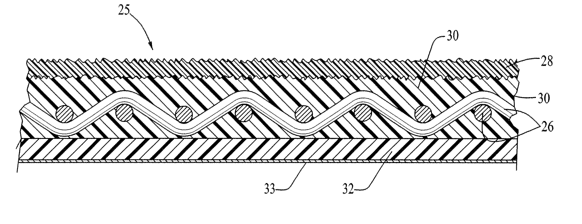
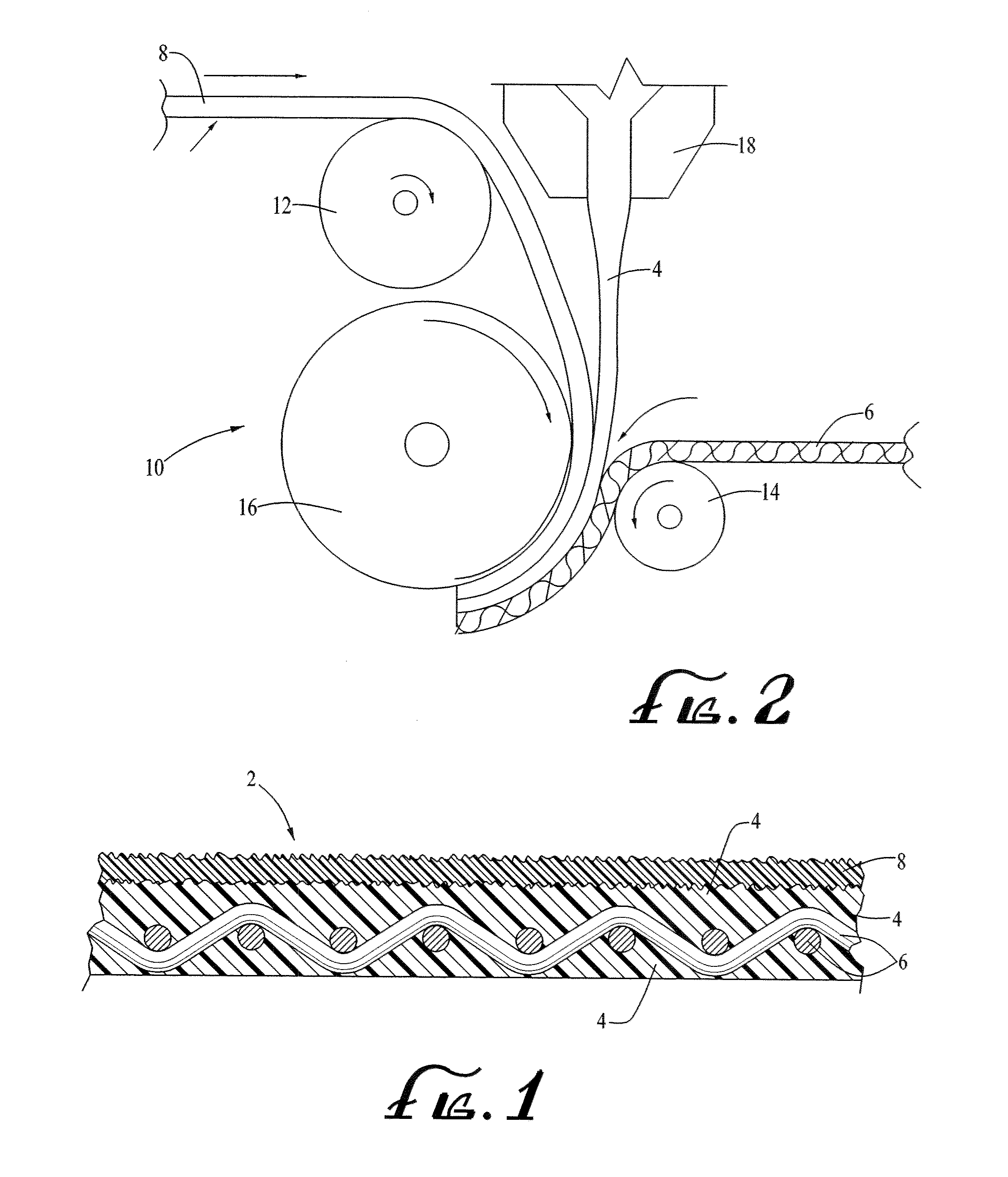
[0022]Referring now to FIG. 1, an enlarged, cross-sectional view of a slip resistant roofing underlayment 2, according to the present invention, is illustrated. The roofing underlayment 2 comprises a scrim 6 woven from polypropylene fibers or tapes, a top layer 8 made from a non-woven polypropylene fabric (spun-bond polypropylene), and a polypropylene coating 4 applied between the scrim 6 and the top layer 8 so as to bond the scrim and the top layer together. The thicknesses of the scrim fabric and the top layer 8 are selected depending on the needs of the particular roofing application.

[0023]During lamination, as described below, the polypropylene coating 4 is impregnated into the weaves of the scrim 6, creating a structural bottom layer comprising the scrim impregnated with the polypropylene coating. This impregnation of the scrim 6 with the polypropylene coating 4 also provides an improved bonding with the non-woven fabric of the top layer 8, thereby reducing the chances of delam...

second embodiment

[0035]The conventional method of installing current synthetic polymer roof underlayments requires a plastic cap attached to a number 12 gauge nail shank. The caps provide a larger surface area to hold the current synthetic polymer roof underlayments to the conventional wood sheathing, plywood or OSB deck, as the heads of the larger nails are needed to increase the nail head-to-underlayment contact area, thus reducing the probability of tearing at the nails. Due to the high tensile strength of the underlayment 25 of the present invention, however, standard ⅜ inch nails can be used for installation without the need for plastic caps. This feature speeds installation, as hand-driven ⅜″ nails install faster without the plastic caps. In addition, a standard ⅜″ coil gun can be used, which is the standard nail gun typically used by asphalt shingle installers. Thus, present invention obviates the need for a separate tool to install the underlayment, while providing better sealing at the nail...


PUM

PropertyMeasurementUnit
temperaturesaaaaaaaaaa
weightaaaaaaaaaa
melting pointaaaaaaaaaa

Abstract

A roofing underlayment having a slip-resistant surface includes a woven polypropylene scrim laminated to a top layer made from a non-woven spun-bond polypropylene fabric. During lamination, the scrim is bonded to the top layer by a polypropylene coating that impregnates the scrim, thereby forming a structural bottom layer comprising the polypropylene-impregnated scrim. The non-woven fibers of the top layer provide a micro-textured, slip-resistant surface. A second polypropylene coating may be applied to the bottom surface of the bottom structural layer. An adhesive layer may optionally be applied either to the bottom surface of the bottom structural layer, or, if used, to the bottom surface of the second polypropylene coating.

Description

CROSS-REFERENCE TO RELATED APPLICATION[0001]Not ApplicableFEDERALLY-SPONSORED RESEARCH OR DEVELOPMENT[0002]Not ApplicableBACKGROUND OF THE INVENTION[0003]This invention relates, in general, to an underlayment for a roof structure, and more specifically, to a roof underlayment having a slip-resistant surface.[0004]Roofing structures for buildings typically include an underlayment positioned between a roof support deck and an overlayment. The overlayment, such as asphalt shingles, tiles, wooden shakes, slate tiles, metal roofing, low-pitch polyurethane spray foam systems, or the like, is intended to provide protection from external weather conditions like wind, rainwater, and snowmelt. The underlayment is installed between the roof deck and the overlayment, and it further protects against moisture and other elements which may pass under the overlayment.[0005]Underlayments have conventionally been produced by coating a layer of organic paper with a certain density of asphalt and are st...

Claims


Application Information

Patent Timeline
Patent Type & Authority Applications(United States)
IPC IPC(8): B32B27/12B32B27/02B32B27/04B32B5/26B32B5/02D04H1/00
CPCB32B5/26Y10T428/24355E04D12/002D04H13/006D04H3/007D04H3/14D06N5/00D06N2201/0254D06N2203/042D06N2207/14Y10T442/102Y10T442/159Y10T442/172Y10T442/176Y10T442/178Y10T442/2738Y10T442/678Y10T442/681
Inventor STRAIT, MARK C.
Owner KIRSCH RES & DEV
Why Eureka
Try Eureka