Device for the Modulation of Cardiac End Diastolic Volume

a diastolic volume and device technology, applied in the direction of suction devices, circulatory assistance devices, therapy, etc., can solve the problems of inability to achieve mechanical efficacy, pharmacotherapy has risks, and the survival and quality of life of patients with severe heart failure remain limited, and achieve small thoracotomy. , the effect of low structural rigidity

Active Publication Date: 2008-01-24
CORINNOVA +1
View PDF24 Cites 36 Cited by
  • Summary
  • Abstract
  • Description
  • Claims
  • Application Information

AI Technical Summary

Benefits of technology

[0040] The present invention also provides a method for delivering a direct cardiac compression heart assist device by creating a heart apex access site and providing a heart periphery with a direct cardiac compression heart assist device contoured to provide curvatures generally in the shape of the heart comprising a resilient inner panel comprising two or more at least partially overlapped membranes having one or more resilient members and contoured to provide curvatures generally in the shape of the heart, wherein the resilient inner panel supplies resistance to the movement of the heart to affect the end-diastolic heart volume, an inflatable outer panel comprising one or more inflatable membranes positioned at least partially around the resilient inner panel to inflate to provide resistance to the movement of the heart to affect the end-systolic heart volume and one or more

Problems solved by technology

Pharmacotherapy is minimally invasive and is a preferred form of treatment for congestive heart failure; however, pharmacotherapy has risks.
Additionally, pharmacotherapy can be ineffective for mechanical problems, such that surgical intervention is necessary.
Nevertheless, the survival and the quality of life of patients with severe heart failure remain limited.
Cardiac transplantation is the only treatment that provides substantial individual benefit, but with fewer than 3,000 donor hearts available worldwide per year, its impact is epidemiologically trivial [Hosenpud et al., 2000].”
A major disadvantage of this device is that the process of the ejection of the blood inverts the curvature

Method used


Image

  • Device for the Modulation of Cardiac End Diastolic Volume
  • Device for the Modulation of Cardiac End Diastolic Volume
  • Device for the Modulation of Cardiac End Diastolic Volume

Examples


example 1

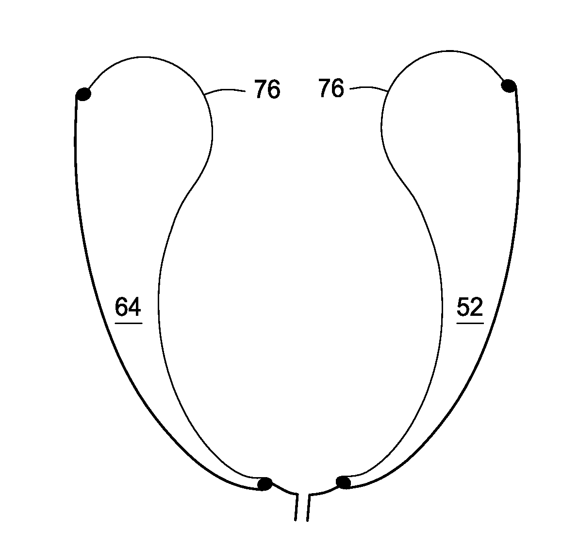
[0132] Direct Cardiac Compression Device. FIGS. 12A and 12B are front view and horizontal cross sectional view of the present invention respectively. FIG. 12A illustrates the device 50 having a surface 78 having a basal edge 80 and an apical edge 84. The surface 78 includes welds 86 to form the chambers 52-74 and include the 4 right ventricle chambers 88 and the 8 left ventricle chambers 90. FIG. 12B illustrates the device 50 having an interior surface 76 on the endocardial side and an exterior surface 92 on the pericardial side. Welds 86 are used to form the chambers 52-74. In some embodiments, the interior surface 76 is made of two mils thick polyethylene and the exterior surface 92 is made of 6 mils thick polyethylene; however the skilled artisan will recognize other thickness (e.g., 0.1 to 12 mils) and other materials may be used.

[0133] By heat welding two polyethylene sheets together along particular folds (as see in FIGS. 12 and 13), a prototype DCCD according to an embodimen...

example 2

[0137] In Vitro Testing. The device of Example 1 was tested on the benchtop and loaded with about 9 kPa of pressure. Based on previous experiments with an earlier device, it was expected to use driving pressures below 5 kPa. An important finding from this benchtop test was that the heart was not ejected from the device when the device was pressurized. This is an important design feature because sewing to the heart will not be needed and interference with the heart valves will be minimal. There were small leaks in the device, but leak proof devices are not required for most uses. Instead, one may place drains to vacuum on the apical end: one in the apical hole to remove air and fluid between the device and heart, and one to remove air and fluid between the device and mediastinum. Lost pneumatic driving fluid may be replaced as necessary.

[0138] This embodiment has also been tested in a live sheep, as expected from the benchtop trials, the device could be easily slipped over the heart...


PUM


Abstract

The present invention provides methods, systems, kits and devices that reduce dyskinesis and hypokinesis. For example, the direct compression cardiac device may be positioned about at least a portion of a heart, and includes a resilient inner panel in contact with at least a portion of the heart periphery, one or more resilient members positioned about the resilient inner panel and at least partially surrounded by an expandable outer panel. The resistance supplied by the inner panel to the heart may be modulated to control the end-diastolic heart volume and remodel the heart, the resistance supplied by the expandable outer panel to the heart may be modulated to control the end-systolic heart volume and remodel the heart or both.

Description

CROSS-REFERENCE TO RELATED APPLICATIONS [0001] This application is a continuation-in-part and claims priority based on U.S. patent application Ser. No. 11 / 400,148, filed Apr. 6, 2006, which claims priority to U.S. Provisional Application Ser. No. 60 / 668,640, filed Apr. 6, 2005, and is related to U.S. patent application Ser. No. 10 / 870,619, filed Jun. 17, 2004, the contents of each is incorporated by reference herein in its entireties.STATEMENT OF FEDERALLY FUNDED RESEARCH [0002] This invention was made with U.S. Government support under Contract No. 4R42HL080759-02 awarded by the NIH. The government has certain rights in this invention.TECHNICAL FIELD OF THE INVENTION [0003] The present invention relates in general to a mechanical interface for the heart of a patient to improve its pumping function, and, more particularly, modulate contraction strain patterns on a diseased or damaged heart in order to reduce dyskinetic or hypokinetic motions. BACKGROUND OF THE INVENTION [0004] Conge...

Claims


Application Information

Patent Timeline
IPC IPC(8): A61M1/12A61N1/362
CPCA61N1/3627A61M1/107A61M60/274A61M60/289A61M60/839A61M60/191A61M60/468
Inventor CRISCIONE, JOHN C.BISWAS, SAURABHHALL, STANHARRISON, LEWISROBBINS, DENNIS
Owner CORINNOVA
Why Eureka
Try Eureka