Intracerebral Blood Flow Measuring Device

a blood flow and measuring device technology, applied in the field of intracerebral blood flow measurement device, can solve the problems of high mortality rate, poor reproducibility of experiments, and many animals used with a lot of costs and a lot of time, and achieves the effect of easy application, sufficient occlusion, and simple preparation for measuremen

Inactive Publication Date: 2008-01-24
HARADA HIDEKI
View PDF7 Cites 3 Cited by
  • Summary
  • Abstract
  • Description
  • Claims
  • Application Information

AI Technical Summary

Benefits of technology

[0031]When the probe holding device according to the present invention is used, the blood flowmeter probe can be disposed between the temporal muscle and the temporal bone. Such disposition of the probe allows the brain blood flow to be measured with the reproducibility and the reliability. When such blood flow measurement is to be carried out, the preparation for the measurement is very simple compared with a conventional method in which a top portion of the cranial bones is removed and the dura mater is exposed. As a result, the Doppler blood flowmeter can be readily applied to th

Problems solved by technology

However, a trauma size of a rat used for the experiment, a subarachnoid hemorrhage rate by means of blood vessel perforation and an early mortality rate between 24 hours and 48 hours after the model preparation depend on a

Method used


Image

  • Intracerebral Blood Flow Measuring Device
  • Intracerebral Blood Flow Measuring Device
  • Intracerebral Blood Flow Measuring Device

Examples


example 1

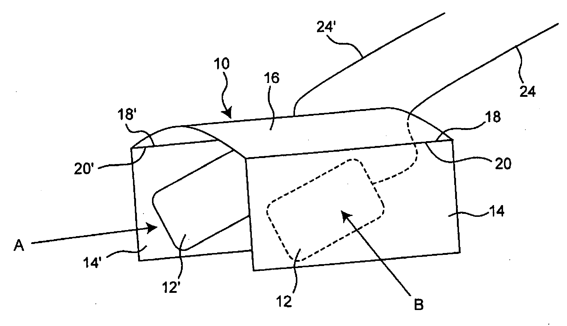
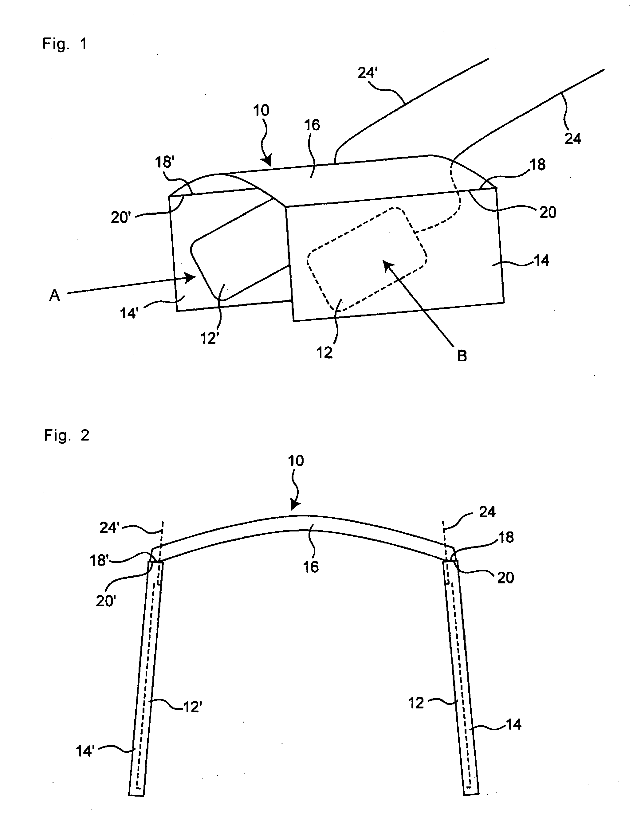
[0066]The blood flowmeter probe was provided to the probe holding device according to the present invention as described above so as to form the blood flowmetry device, with which the MCAO model experiments were carried out using rats as follows. It is noted that the device used was as shown in FIGS. 1 and 2, but it comprised only one prove holding member. That is, the device was composed of only the blood flowmeter probe 12 and the probe holding member 14. A conductor 24 was connected to the blood flowmeter.

[0067]1. Preparation for Surgery

[0068]The rats were anesthetized with inhaled 5% concentration of isoflurane in oxygen. The trachea was then intubated and lungs were mechanically ventilated with a carrier gas of 30% oxygen and 70% nitrogen. The end-tidal concentration of isoflurane was reduced to 2.5%. The pericranial temperature was automatically controlled to 37.0° C. (Mon-a-therm 7000 of Mallinckrodt Inc. was used) by surface heating or cooling. A cannula was inserted in the ...

example 2

[0089]As shown in FIG. 8, a device was produced by positioning, in a zigzag manner, an electrical resistor having a line form as a heating element as well as a temperature sensor in the area 40 of the bridging part 16 of the probe holding device 10 followed by covering them with a silicone resin. The skull by incision of the skull tissue of the rat was exposed similarly to the above, followed by positioning the probe holding members in the both side natural pockets each between the temporal muscle and the lateral aspect of the skull, so that thus produced device was attached to the rat.

[0090]The heating was controlled so as to keep the detected temperature of the temperature sensor at 37.0° C. During the three and a half hours of the oxygen-air-isoflurane anesthesia, a rectal temperature of the rat was lowered to 34.5° C. from the initial temperature of 37° C. while the temperature under the temporal muscle was at lowest 36.8° C. so that it has been confirmed that the brain temperat...


PUM


Abstract

It is intended to standardize MCAO model and to further improve the reproducibility and reliability thereof. There is provided a probe holding device (10) which includes a probe holding member (14) for holding a blood flowmeter probe (12), and such device is used together with the blood flowmeter probe when measuring intracerebral blood flow. While holding the blood flowmeter, the probe holding member can be disposed in a position of being adjacent to and outside temporal bones.

Description

TECHNICAL FIELD[0001]The present invention relates to a device which measures a blood flow such as a blood flow rate in a brain, and particularly in a brain portion which is located closely to a temporal bone(s). The present device is preferably applicable to intracerebral blood flow measurement in various experiments in which animals such as rats, mice or the like are used.BACKGROUND ART[0002]Middle Cerebral Artery Occlusion, MCAO) model was proposed by Koizumi and Zea Longa et. al. in which a rat was used with an intraluminal filament, and such model has been used for the mechanism analysis as well as new therapy research and development as to ischemic cell death in brain (see Non-Patent References 1 and 2 mentioned below). This model is advantageous in that it is relatively easily carried out and less-invasive, and that craniotomy which affects blood-brain barrier permeability, brain pressure, and brain tissues is not required.[0003]However, a trauma size of a rat used for the ex...

Claims


Application Information

Patent Timeline
IPC IPC(8): A61B5/026
CPCA61B5/02055A61B5/0261A61B2503/40A61B8/06A61B5/6814A61B5/4064
Inventor HARADA, HIDEKI
Owner HARADA HIDEKI
Why Eureka
Try Eureka