
Solar cell with nanostructure electrode

a nano-structure electrode and solar cell technology, applied in the field of solar cells, can solve the problems of affecting the underlying active layer(s), increasing the cost of c-, and rapidly becoming a scarce commodity

Inactive Publication Date: 2008-01-31
RGT UNIV OF CALIFORNIA +1
View PDF27 Cites 45 Cited by
  • Summary
  • Abstract
  • Description
  • Claims
  • Application Information

AI Technical Summary

Benefits of technology

[0015] Other features and advantages of the invention will be apparent from the accompanying drawings and from the detailed description. One or more of the above-disclosed embodiments, in addition to certain alternatives, are provided in further detail below with reference to the attached figures. The invention is not limited to any particular embodiment disclosed.

Problems solved by technology

However, the high cost of c-Si wafers has led the industry to research alternate, and generally less-expensive, solar cell materials.
However, ITO can be an inadequate solution for many emerging applications (e.g., non-rigid solar cells, due to ITO's brittle nature), and the indium component of ITO is rapidly becoming a scarce commodity.
Moreover, deposition of transparent conducting oxides (TCOs) for minimal light loss normally requires a sputtering process, which can severely damage the underlying active layer(s).

Method used


Image

  • Solar cell with nanostructure electrode
  • Solar cell with nanostructure electrode
  • Solar cell with nanostructure electrode

Examples


Embodiment Construction

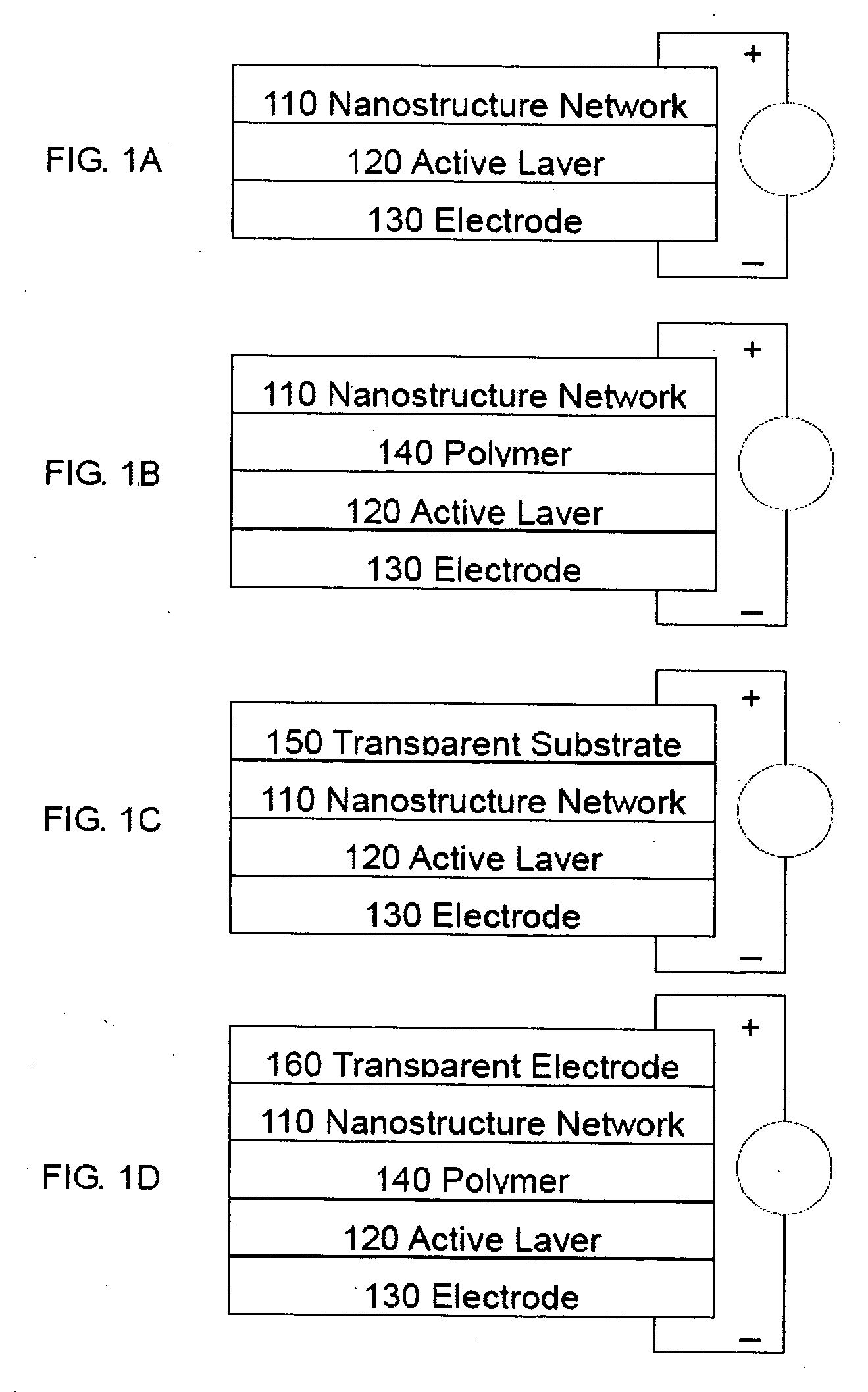
[0025] Referring to FIG. 1A, an optoelectronic device according to an embodiment of the present invention comprises a nanostructure network 110, an active layer 120 and an electrode 130. This device may be a solar cell, which is a semiconductor device that converts photons from the sun (solar light) into electricity. Fundamentally, the device needs to photo-generate charge carriers (e.g., electrons and holes) in an active layer, and separate the charge carriers to a conductive electrode that will transmit the electricity.

[0026] The active layer 120 is preferably a strong light absorber such as, for example, one based on silicon (e.g., amorphous, protocrystalline, nanocrystalline), cadmium telluride (CdTe), copper indium gallium selenide (CIGS), chalcogenide films of copper indium selenide (CIS), gallium arsenide (GaAs), light absorbing dyes, quantum dots, organic semiconductors (e.g., polymers and small-molecule compounds like polyphenylene vinylene, copper phthalocyanine and carbo...


PUM

PropertyMeasurementUnit
sheet resistanceaaaaaaaaaa

Abstract

An optoelectronic device comprising at least one nanostructure-film electrode and fabrication methods thereof are discussed. The optoelectronic device may further comprise a different material to fill in porosity in the nanostructure-film. Additionally, the optoelectronic device may be a solar cell, comprising at least one of a variety of photosensitive active layers.

Description

CROSS-REFERENCE TO RELATED PATENT APPLICATIONS [0001] This application claims priority to U.S. Provisional Patent Application No. 60 / 833,845, filed Jul. 28, 2006, and entitled “ORGANIC SOLAR CELLS WITH CARBON NANOTUBE NETWORK ELECTRODES,” and PCT Application No. US / 2005 / 047315, filed Dec. 27, 2005, and entitled “COMPONENTS AND DEVICES FORMED USING NANOSCALE MATERIALS AND METHODS OF PRODUCTION,” which are herein incorporated by reference.COPYRIGHT & TRADEMARK NOTICE [0002] A portion of the disclosure of this patent document contains material that is subject to copyright protection. The owner has no objection to the facsimile reproduction by any one of the patent document or the patent disclosure, as it appears in the Patent and Trademark Office patent file or records, but otherwise reserves all copyrights whatsoever. [0003] Certain marks referenced herein may be common law or registered trademarks of third parties affiliated or unaffiliated with the applicant or the assignee. Use of ...

Claims


Application Information

Patent Timeline
Patent Type & Authority Applications(United States)
IPC IPC(8): H01L31/04B05D5/12B82B1/00B82B3/00
CPCB82Y10/00B82Y20/00H01L31/022425H01L51/0036Y02E10/549H01L51/0038H01L51/0047H01L51/4253H01L51/444H01L51/0037H10K85/113H10K85/1135H10K85/114H10K85/215H10K30/821H10K30/50H10K30/35H10K30/30
Inventor HU, LIANGBINGGRUNER, GEORGEHECHT, DAVIDROWELL, MICHAELTOPINKA, MARKMCGEHEE, MICHAEL
Owner RGT UNIV OF CALIFORNIA
Learn More