
Piping design for high density plasma process chamber

a plasma process chamber and plasma technology, applied in pipeline systems, thin material processing, servomotor components, etc., can solve the problems of fabrication failure, explosive poisonous gas, and inability to detect a minute gas leakage, so as to prevent the process from failure and solve the problem of residual gas

Inactive Publication Date: 2008-01-31
GRACE SEMICON MFG CORP
View PDF9 Cites 1 Cited by
  • Summary
  • Abstract
  • Description
  • Claims
  • Application Information

AI Technical Summary

Benefits of technology

[0008]The primary objective of the present invention is to provide a piping design for a high density plasma process chamber to effectively solve the problem of the residual gas inside the process piping and prevent the process from failure.
[0009]Another objective of the present invention is to provide a piping design for a high density plasma process chamber to fabricate a high-reliability film, reduce the process failures, lower the defective fraction of products, and save the fabrication cost.

Problems solved by technology

However, silane is an explosive poisonous gas.
Therefore, silane is not allowed to leak from or remain inside the gas piping in any fabrication process.
However, MFC is unlikely to detect a minute gas leakage.
In the deposition process of a dielectric film, the leakage or residual of silane implies the danger of explosion and the problem of fabrication failure.

Method used


Image

  • Piping design for high density plasma process chamber
  • Piping design for high density plasma process chamber

Examples


Embodiment Construction

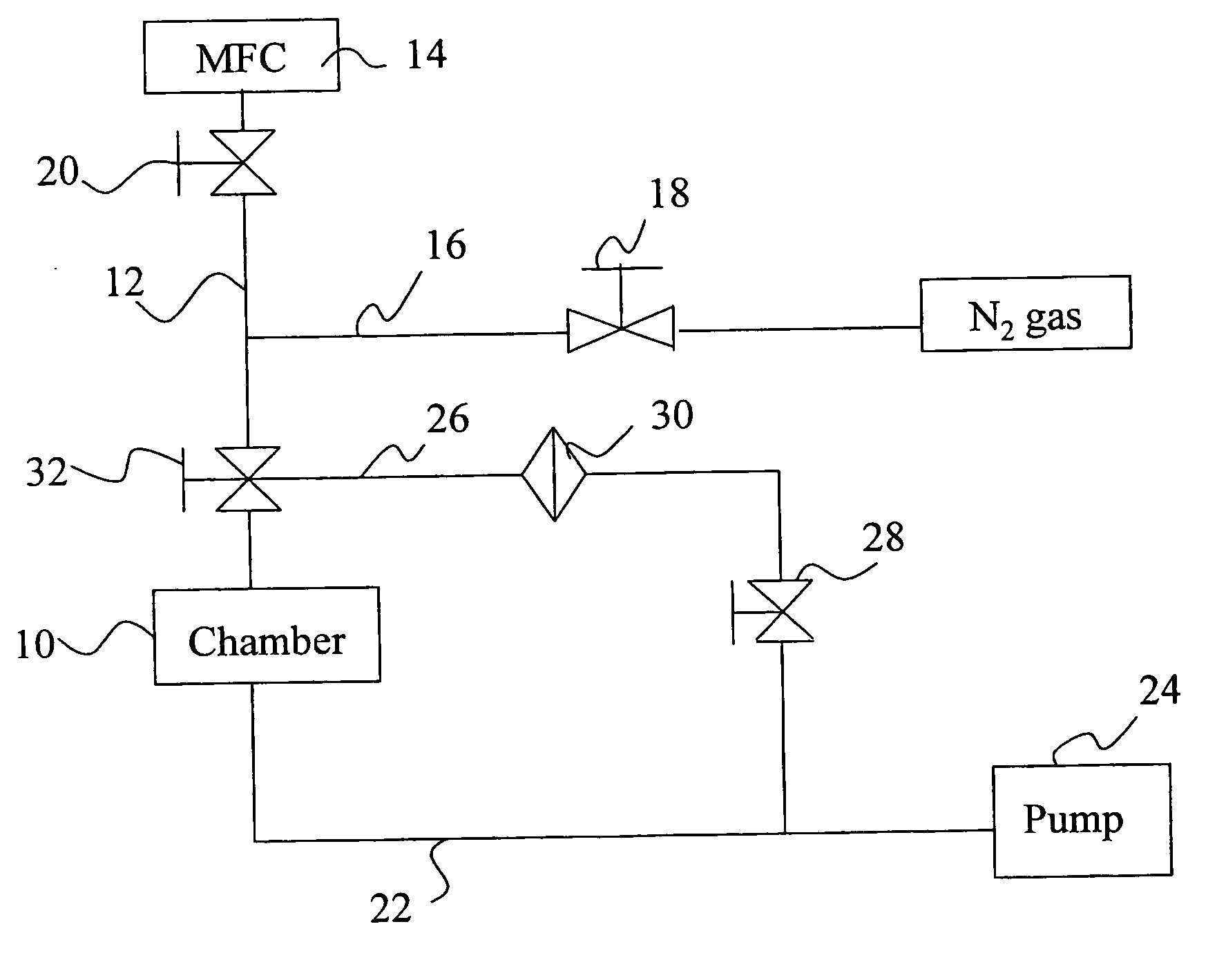
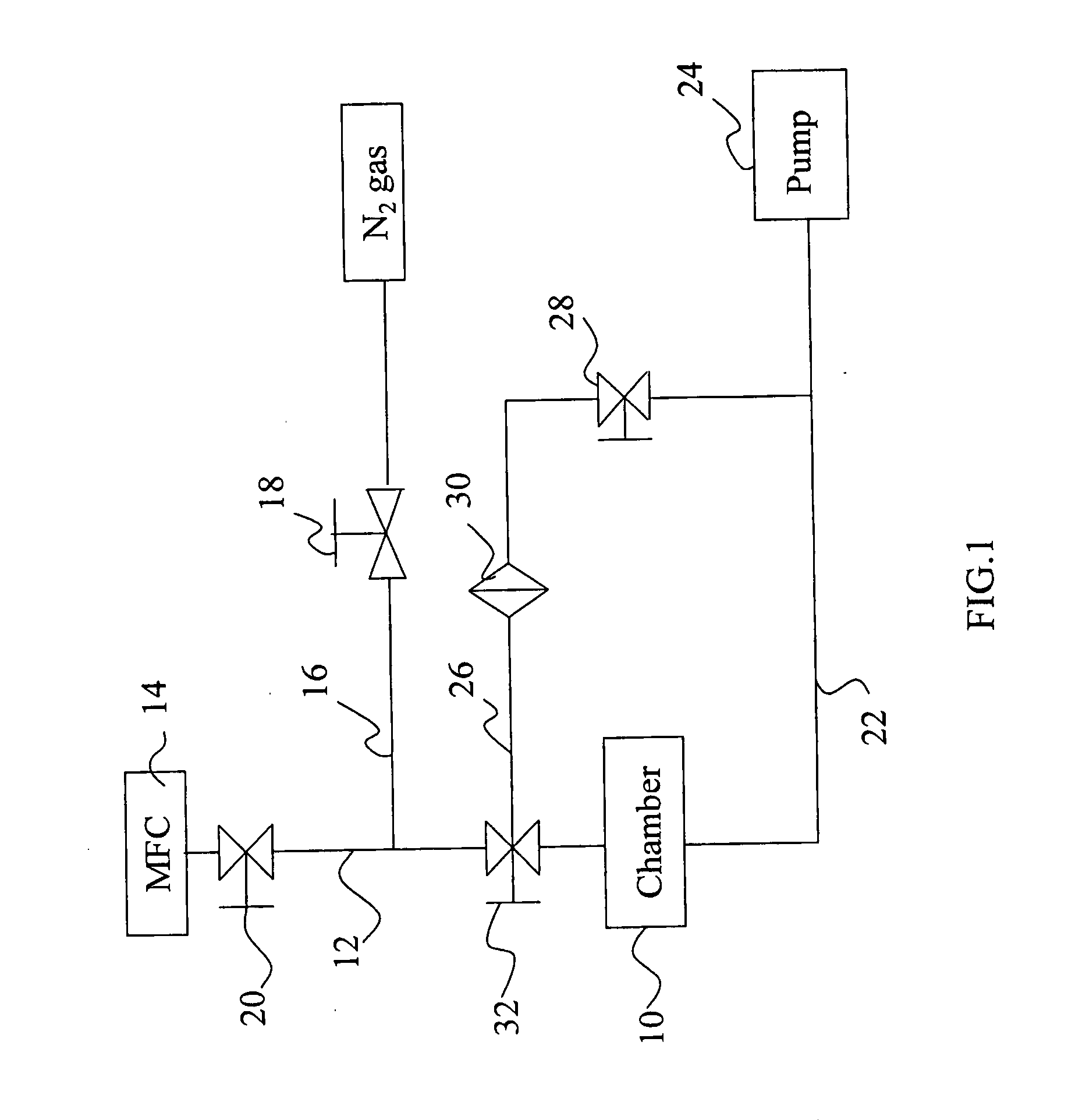
[0013]The present invention pertains to a piping design for a high density plasma process chamber. Refer to FIG. 1 a diagram schematically showing the piping design according to the present invention. In FIG. 1, a simpler gas piping for a high density plasma process chamber is used to exemplify the present invention. However, the equivalent modifications or variations realized by the persons skilled in the art, including the modification of valve positions and the layout of the chamber-purge piping, are to be also included within the scope of the present invention.

[0014]As shown in FIG. 1, the piping design for a high density plasma process chamber of the present invention comprises: a gas injection pipe 12, a gas exhaust pipe 22 and an extra pipe 26. The gas injection pipe 12 is used to transport a process gas to a process chamber 10, and a mass flow controller (MFC) 14 is installed on the gas inject piping 12 to monitor the mass flow rate of the injected gas. A chamber-purge pipe ...


PUM


Abstract

The present invention discloses a piping design for a high density plasma process chamber, wherein an extra pipe is added to between a process chamber and a mass flow controller, and the extra pipe together with a pump is used to drain out the gas, which cannot be monitored by the mass flow controller and survives in a gas injection pipe, lest the remaining gas pollute the deposited film or react with the process gas to induce an explosion in the succeeding deposition process.

Description

BACKGROUND OF THE INVENTION[0001]1. Field of the Invention[0002]The present invention relates to a piping design for a high density plasma process chamber, whereby the gas remaining in the front piping of a process chamber is pumped out lest a pollutant reaction occur in the succeeding film-deposition process.[0003]2. Description of the Related Art[0004]High Density Plasma (HDP) has a high concentration of plasmarized ions and is usually used in the gap-fill process or the film-deposition process of a high density material. In current VLSI fabrication, HDP is often used in the deposition process of a silicide dielectric layer.[0005]Silicon may come from an inorganic source or an organic source. In addition to non-speciality gases (such as N2 and O2), silane (SiH4) is a speciality gas widely used in the current semiconductor industry. As silane has a very low boiling point of about −112° C., it is in the gaseous state at a normal temperature. However, silane is an explosive poisonous...

Claims


Application Information

Patent Timeline
IPC IPC(8): F17D1/00
CPCF17D1/086Y10T137/87185
Inventor CHANG, PING-YIZHANG, XIAO-PING
Owner GRACE SEMICON MFG CORP
Learn More