Sputtering Apparatus and Method, and Sputtering Control Program

a technology of sputtering control and sputtering apparatus, which is applied in the direction of electrolysis components, vacuum evaporation coatings, coatings, etc., can solve the problems of not focusing on scraping the target, and deteriorating the uniformity of the film thickness. , to achieve the effect of deteriorating the uniformity of the film thickness

Inactive Publication Date: 2008-01-31
SHIBAURA MECHATRONICS CORP
View PDF2 Cites 28 Cited by
  • Summary
  • Abstract
  • Description
  • Claims
  • Application Information

AI Technical Summary

Benefits of technology

[0020] In a preferred aspect, the number of rotations of the magnet unit is switched from a large number of rotations to a small number of rotations as the use time or the usage of the target increases.
[0021] In the above aspects, a large number of rotations which is optimum in the beginning of the use

Problems solved by technology

Specifically, even if the uniformity of the film thickness is good in the beginning of the use of the target, the problem is that the uniformity of the film thickness worsens in the end of the use of the target.
However, these technologies do not focus on scraping of the target which occurs over time, and thus cannot prevent gradual deterioration of the uniformity of the film thickness in the products which are successively produced between the beginning and end of the use of the target.
H9-176852 require not only a mechanism for rotating the permanent magnet unit but also a mechanism for moving the permanent magnet unit up and down to adjust the distance thereof to the target, thus the apparatus becomes complicated and the costs are increased.
H10-60640, provision of the rotating electromagnetic coil complicates the apparatus and increases the costs, and it is extremely troublesome to adjust the exciting electric power to be supplied to the electromagnetic coil to an optimum value.
On the other hand, there are the following difficulties in applying the technologies described in Japanese Patent Application Laid-Open No.
H10-195649 the number of rotations of the magnet is merely controlled by a fixed number of rotations in accorda

Method used


Image

  • Sputtering Apparatus and Method, and Sputtering Control Program
  • Sputtering Apparatus and Method, and Sputtering Control Program
  • Sputtering Apparatus and Method, and Sputtering Control Program

Examples


embodiment

[0047]FIG. 7 shows a result of the experiment based on the present invention described above. In the present experiment, for example, a semi-transparent film is formed on each of material substrates of one-sided / dual layer DVDs, and the uniformity of the semi-transparent film formed on each substrate (MAX−MIN / MAX+MIN)×100[%] is measured with respect to a target life (WH) shown with the power consumption corresponding to an increase in the number of processed substrates.

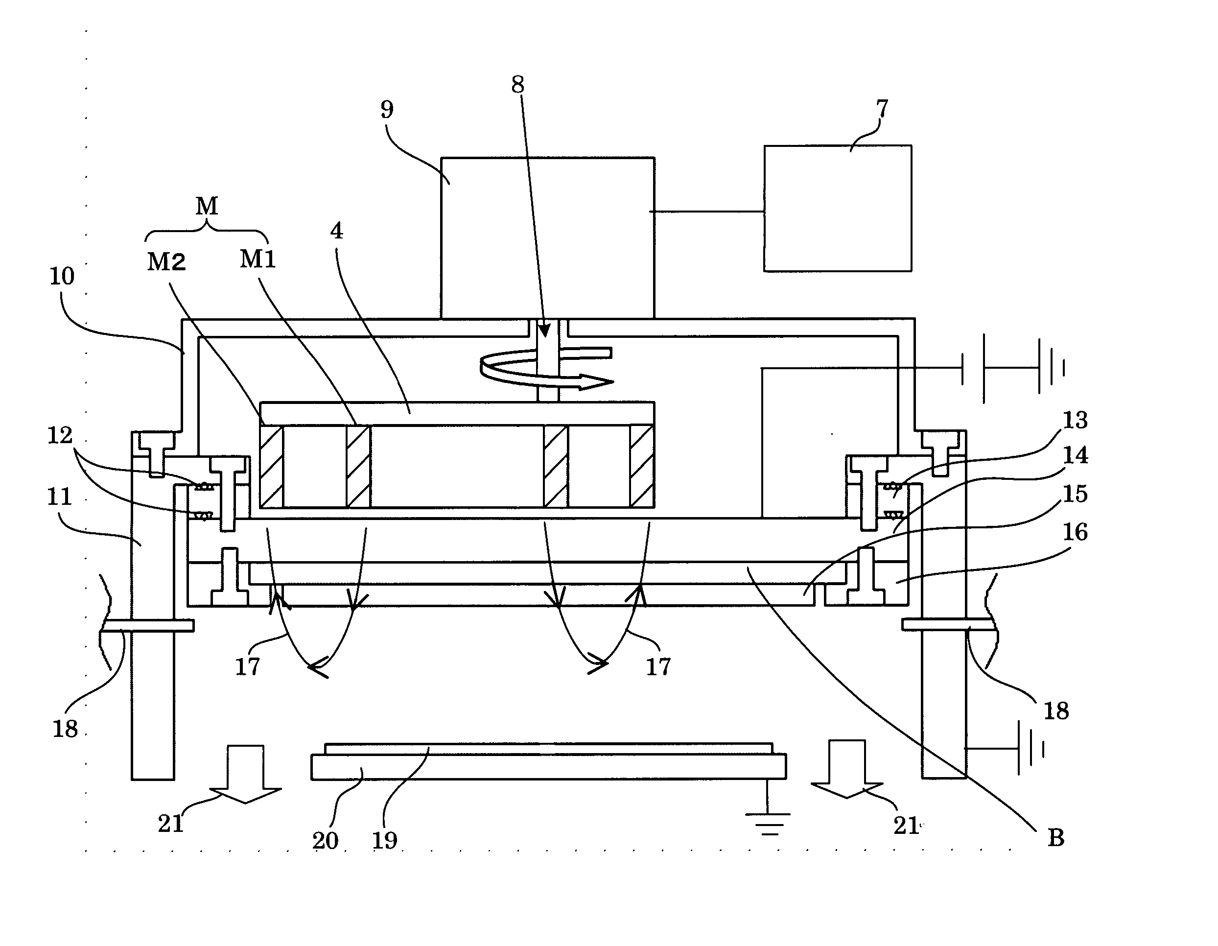
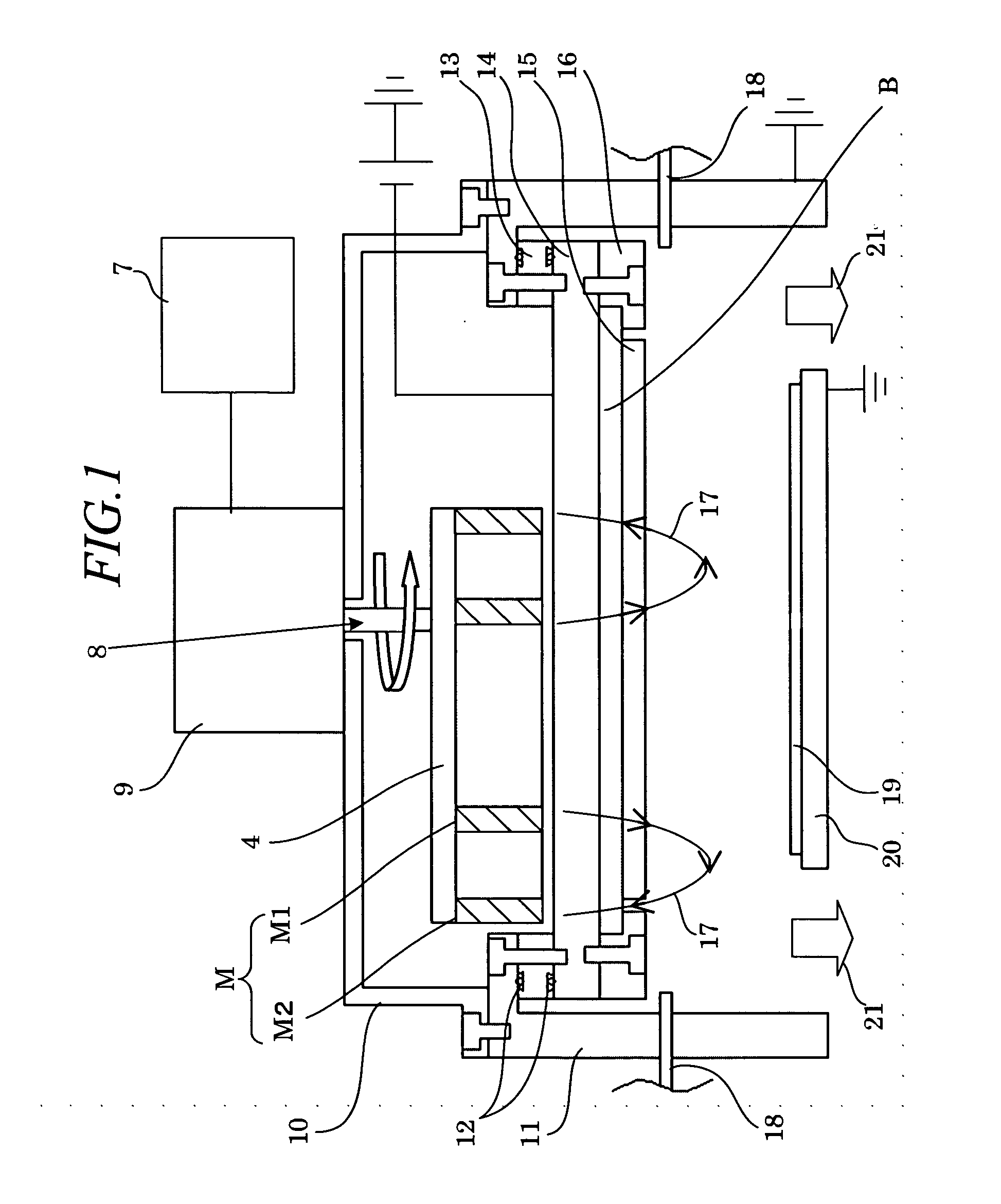
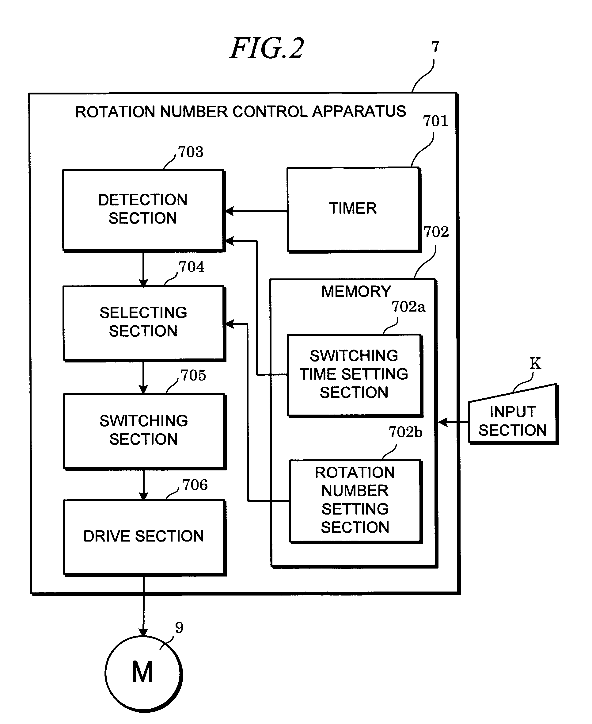
[0048] First of all, in the case where the number of rotations of the target 15 was kept constant at 180 [rpm], which is set as an optimum value in the beginning of the use of the target, without applying the present invention, the distribution exhibited a declining trend upon reaching the target life of 15000 [WH], and increased to ±3 [%] or higher in the vicinity of 35000 [WH]. On the other hand, in the case where the number of rotations of the target 15 was reduced to 120 [rpm] in the vicinity of the target life o...


PUM

PropertyMeasurementUnit
Thicknessaaaaaaaaaa
Densityaaaaaaaaaa

Abstract

To provide a sputtering apparatus and method, and a sputtering control program which are configured simply and can secure the uniformity of the film thickness from the beginning to the end of the use of a target.
There are provided: a target 15 disposed so as to face an object to be treated 19; a permanent magnet unit M which generates a high-density plasma by means of a magnetic field and deposits a material of the target 15 on the object to be treated, in the form of a film; a rotational mechanism 9 which rotates the permanent magnet unit M; and a rotation number control apparatus 7 which gradually changes the number of rotations of the permanent magnet unit M rotated by the rotational mechanism 9. The rotation number control apparatus 7 has a rotation number setting section 702b for setting the number of rotations to be switched, a switching time setting section 702a for setting the time for switching, a detection section 703 for detecting the switching time, a selecting section 704 for selecting the number of rotations at the switching time, and a switching section 705 for outputting an instruction of switching to the selected number of rotations.

Description

TECHNICAL FIELD [0001] The present invention relates to a spattering apparatus and method, as well as a sputtering control program for depositing a reflective film, permeable film, or other thin film made from metal or an insulator, on a surface of an object to be treated by means of, for example, a sputter source. BACKGROUND ART [0002] Recently, in a manufacturing process for producing various products such a semiconductor device, liquid crystal display, or optical disk, there has been widely used a sputtering deposition apparatus (referred to as “sputtering apparatus” hereinafter) for depositing a thin film of various types on an object to be treated such as a wafer, glass substrate, polycarbonate substrate, or the like. In such a sputtering apparatus, a predetermined deposited material as a target, which is provided inside a vacuum container, is biased to the cathode beforehand, and ions of discharge gas such as argon (Ar) are collided with the target, whereby the desorbed materi...

Claims


Application Information

Patent Timeline
IPC IPC(8): C23C14/35C23C14/34C23C14/54G11B7/26
CPCC23C14/35C23C14/542C23C14/54C23C14/358
Inventor KUROIWA, SHUNJI
Owner SHIBAURA MECHATRONICS CORP
Why Eureka
Try Eureka