LED lighting device

a technology of led lighting and diodes, which is applied in the direction of lighting and heating apparatus, semiconductor devices for light sources, instruments, etc., can solve the problems of reducing the penetration of light, deteriorating resin, shortening the life of led, etc., and achieves the effect of improving heat radiation efficiency, reducing the number of leds, and controlling temperature ris

Inactive Publication Date: 2008-01-31
ATEX CO LTD
View PDF1 Cites 137 Cited by
  • Summary
  • Abstract
  • Description
  • Claims
  • Application Information

AI Technical Summary

Benefits of technology

[0018]In the second structure of the light emission part and the heat radiator as described above, heat which is generated in a junction and an encapsulating resin part of a plurality of LED chips heated by lighting is transmitted from the substrate attaching face of the heat radiation base to an area of lower temperature. In other words, the fins formed on a surface of the heat radiation base have contact with ambient air and thus is cooled by convection of the air or the like. In the present invention, since the fins for heat radiation are provided not only on the outer periphery of the heat radiation base but also on the inner periphery of the hole of the heat radiation base, efficiency of heat radiation is improved, and temperature rise can be controlled even when a plurality of high-density LEDs are mounted.
[0019]In the second structure, if another set of heat radiation fins are formed on a rear surface of the heat radiation base, convection of the air flowing up and down is brought into contact with the fins on either of the outer periphery of the heat radiation base, the inner periphery of the hole, or the rear surface of the heat radiation base irrespective of the arranging direction of the LED lighting device, thereby improving the heat radiation effect.

Problems solved by technology

Due to this heat, the resin deteriorates with the passage of time.
Such deterioration of resin leads to a decrease in penetration of light, which shortens the lifespan of the LED.
Furthermore, when several white LEDs are mounted to produce a lighting device, the total heat value becomes large, requiring more efficient cooling means.
On the other hand, the heat not only from LEDs but also from power source units render the design for heat radiation complicated requiring the release of the heat from both parts.
Insufficient heat radiation and low cooling efficiency shortens the lifespan as an LED lighting device.

Method used


Image

  • LED lighting device
  • LED lighting device
  • LED lighting device

Examples


first embodiment

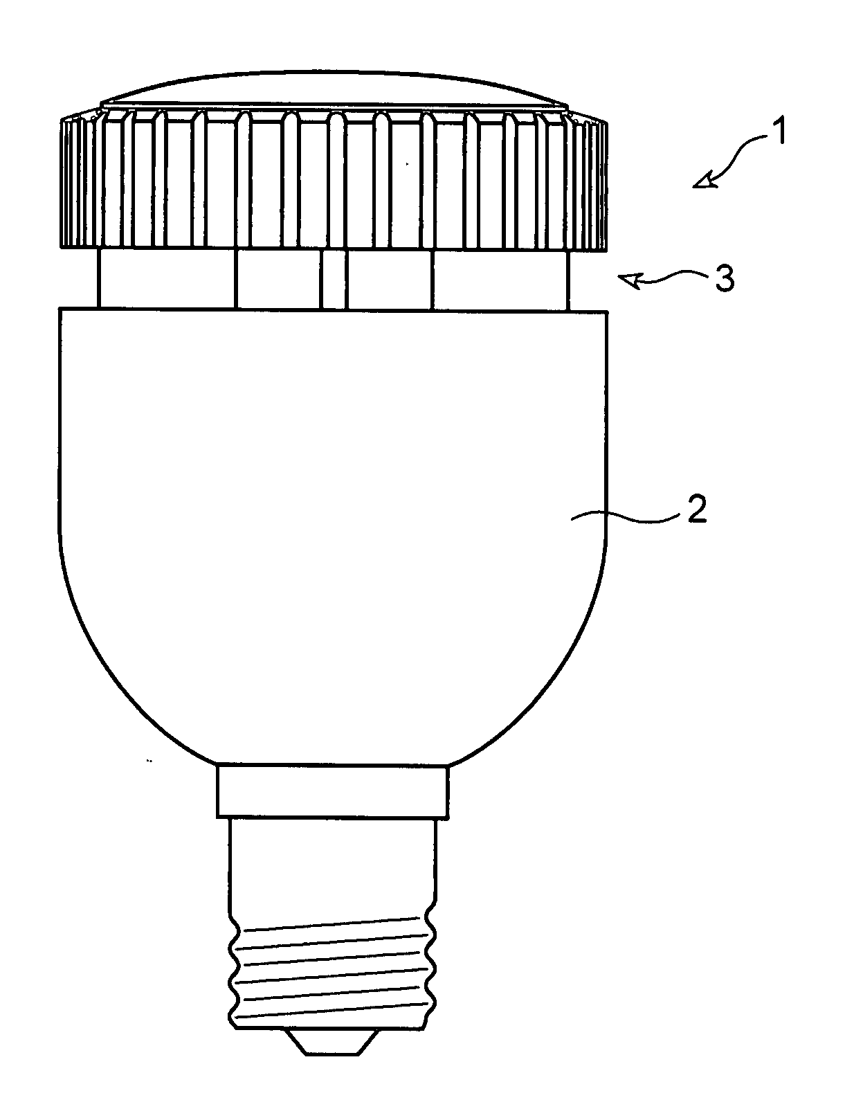
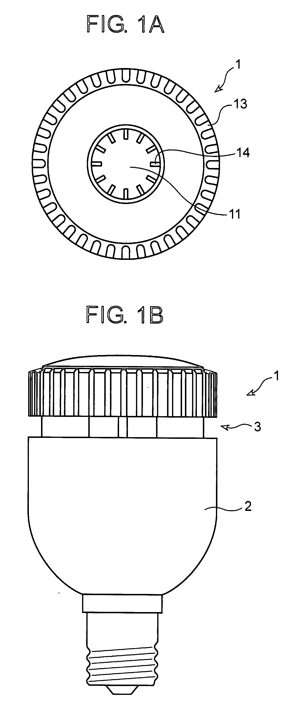
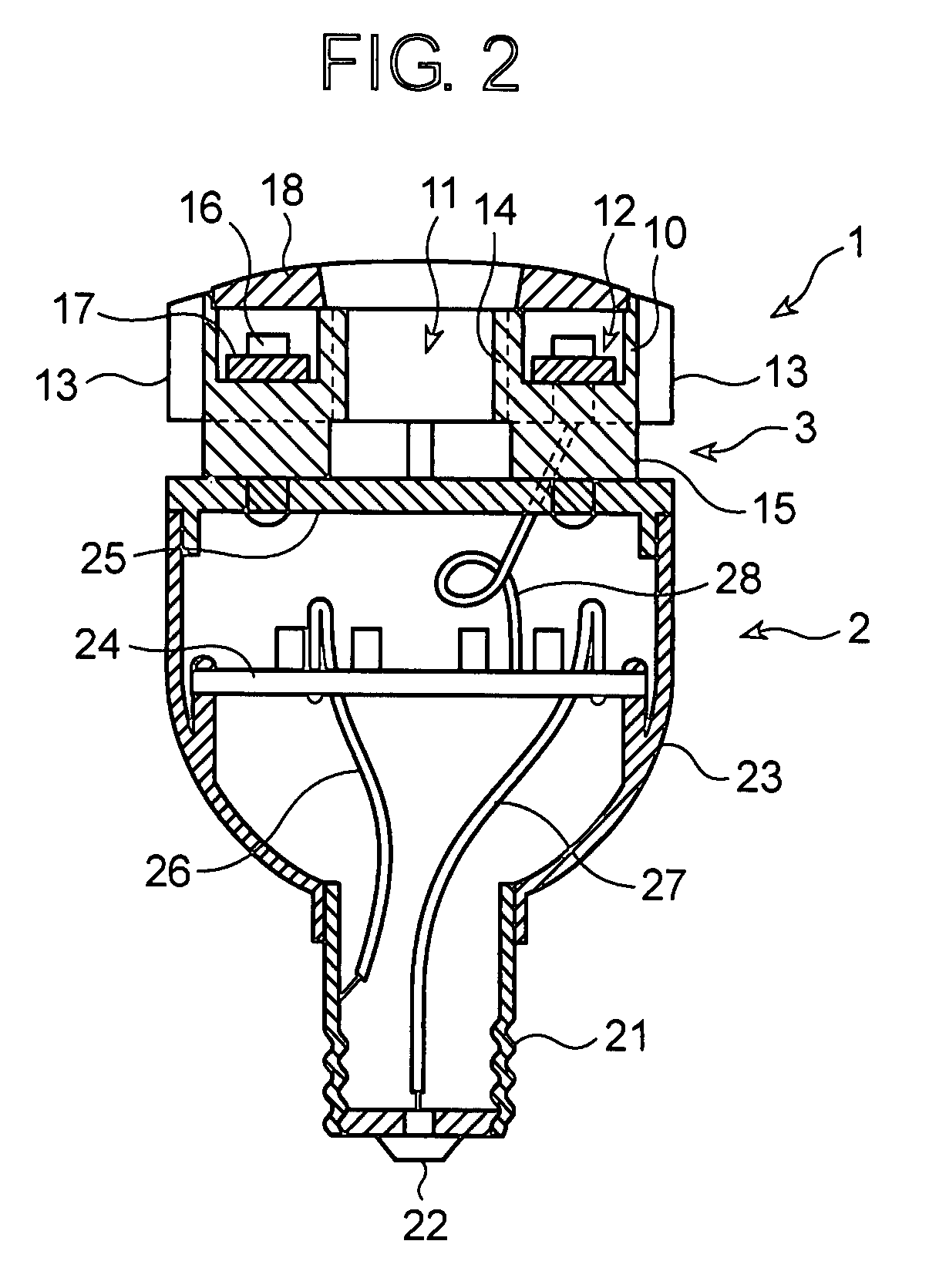
[0032]An LED lighting device according to the present invention is composed of a light emission part 1 provided with LEDs and a heat radiator for the LEDs, a power source part 2 generating a current to be supplied to the LEDs from a commercial power source, and an air circulation part 3 for circulating ambient air. The light emission part 1 and the power source part 2 are thermally separated by the air circulation part 3. The light emission part 1 is, as shown in FIG. 2, provided with a heat radiation base 10 made of aluminum alloy which basically has an annular shape having a hole 11 at a central portion thereof. The heat radiation base 10 has, on one face (front face) which is perpendicular to a central axis of the hole 11, a substrate attaching face 12 for attaching an LED substrate 17 on which a plurality of LED chips 16 are mounted in a circular pattern. On an outer periphery of the heat radiation base 10 and on an inner periphery of the hole 11, fins 13 and 14 are integrally f...

second embodiment

[0040]FIG. 4A is a front view illustrating an LED lighting device according to the present invention, and FIG. 4B is a side view illustrating the LED lighting device in FIG. 4A.

[0041]As shown in FIG. 4A, an LED lighting device according to the second embodiment of the present invention is composed of a light emission part 1 provided with LEDs and a heat radiator for the LEDs, a power source part 2 generating a current to be supplied to the LEDs from a commercial power source, and an air circulation part 3 for circulating ambient air. The light emission part 1 and the power source part 2 are thermally separated by the air circulation part 3. The light emission part 1 is provided with a heat radiation base 30 made of aluminum alloy which basically has an annular shape having a hole 31 at a central portion thereof. On an outer periphery of the heat radiation base 30 and an inner periphery of the hole 31, fins 32 and 33 are integrally formed, respectively. On a rear surface of the heat ...


PUM


Abstract

An LED lighting device has high cooling efficiency and long life with a plurality of high-intensity LEDs mounted thereto. The LED lighting device is composed of a light emission part provided with a plurality of LEDs and a heat radiator for the LEDs, a power source part generating a current to be supplied to the LEDs from a commercial power source, and an air circulation part for circulating ambient air. The light emission part and the power source part are thermally separated by the air circulation part. The light emission part is provided with an annular heat radiation base having a hole formed at a central portion thereof and a substrate attaching face formed around the hole, and an LED substrate which is attached to the substrate attaching face and on which a plurality of LED chips are mounted. The heat radiation base has heat radiation fins as the heat radiator which are formed on an outer periphery of the heat radiation base and on an inner periphery of the hole. By the presence of the air circulating part, little heat generated from the power source part is transmitted to the light emission part. Therefore, it is possible to accomplish desired designing of heat radiation of the light emission part concerned with intensity and life of an LED, which is critical to performance of an LED lighting device.

Description

BACKGROUND OF THE INVENTION[0001]1. Field of the Invention[0002]The present invention relates to an LED (light-emitting diode) lighting device capable of controlling temperature rise of an LED which is a problem when using a high-intensity LED as a lighting device.[0003]2. Description of the Related Art[0004]As commercialization of blue LEDs and white LEDs was realized, researches for employing LEDs instead of incandescent light bulbs or fluorescent lamps as a light source for lighting devices have been conducted, and some LED lighting devices have already been produced on a commercial basis.[0005]In the case of an LED using a chip having a p-n junction composed of a p-type semiconductor and an n-type semiconductor, when a voltage is applied to the LED chip in a forward direction, a current flowing in the p-type semiconductor (a hole) and an electron flowing in the n-type semiconductor that collide with each other recombine around the junction. Then, the initial energy of the electr...

Claims


Application Information

Patent Timeline
Patent Type & Authority Applications(United States)
IPC IPC(8): F21V29/00
CPCF21V29/004F21Y2101/02F21V23/023F21V29/75F21V29/76F21V23/002F21V29/773F21V29/80F21V29/83F21K9/137F21V29/763F21K9/233F21Y2115/10G02F1/133603F21V29/60
Inventor ISHIBASHI, KAZUO
Owner ATEX CO LTD
Why Eureka
Try Eureka