High Voltage Transformer

Inactive Publication Date: 2008-01-31
MINEBEA CO LTD
View PDF2 Cites 17 Cited by
  • Summary
  • Abstract
  • Description
  • Claims
  • Application Information

AI Technical Summary

Benefits of technology

[0007] The present invention has been made in light of the problems described above, and it is an object of the present invention to provide a high voltage transformer in which a primary winding can be positioned selectively and optimally with respect to a secondary winding, and so the primary winding is allowed to be tightly coupled electromagnetically to the secondary winding, while the workability in assembly is improved.
[0013] Accordingly, since the primary winding and the secondary winding can be disposed close to each other on the same axis, the electromagnetic coupling between the primary and secondary windings is enhanced, which improves the efficiency of the transformer. Also, since the primary winding is composed of thin conductive sheet coils coated with resin, the insulation from the secondary winding is ensured, the assembling workability is enhanced, and the number and arrangement of the coils can be arbitrarily and optimally selected allowing the coupling coefficient of the transformer to be adjusted. Consequently, the transformer characteristics and the component standardization can be achieved.

Problems solved by technology

In the high voltage transformer of FIG. 13, the primary winding is capable of carrying a large current, but because the primary winding and the secondary winding are disposed in a tandem arrangement along the same axis, there is provided a poor electromagnetic coupling therebetween.
Accordingly, the high voltage transformer of FIG. 13, when adapted as a transformer with a high coupling between the primary and secondary windings, namely a tightly-coupled transformer, is caused to behave with deteriorated performance.
Also, the sheet coil constituting the primary winding and inserted in the opening of the bobbin must be coated with a thick resin in order to secure insulation, which deteriorates the workability.

Method used


Image

  • High Voltage Transformer
  • High Voltage Transformer
  • High Voltage Transformer

Examples


Embodiment Construction

[0027] An exemplary embodiment of the present invention will hereinafter be described with reference to the accompanying drawings.

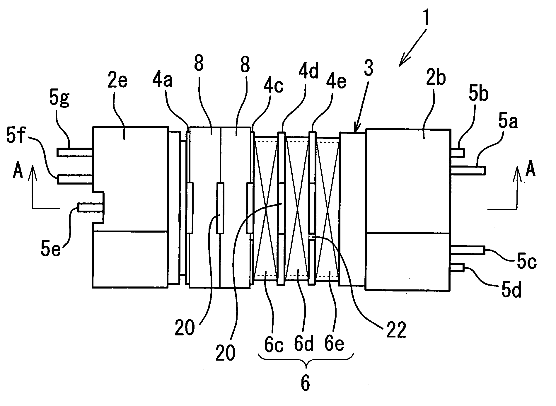
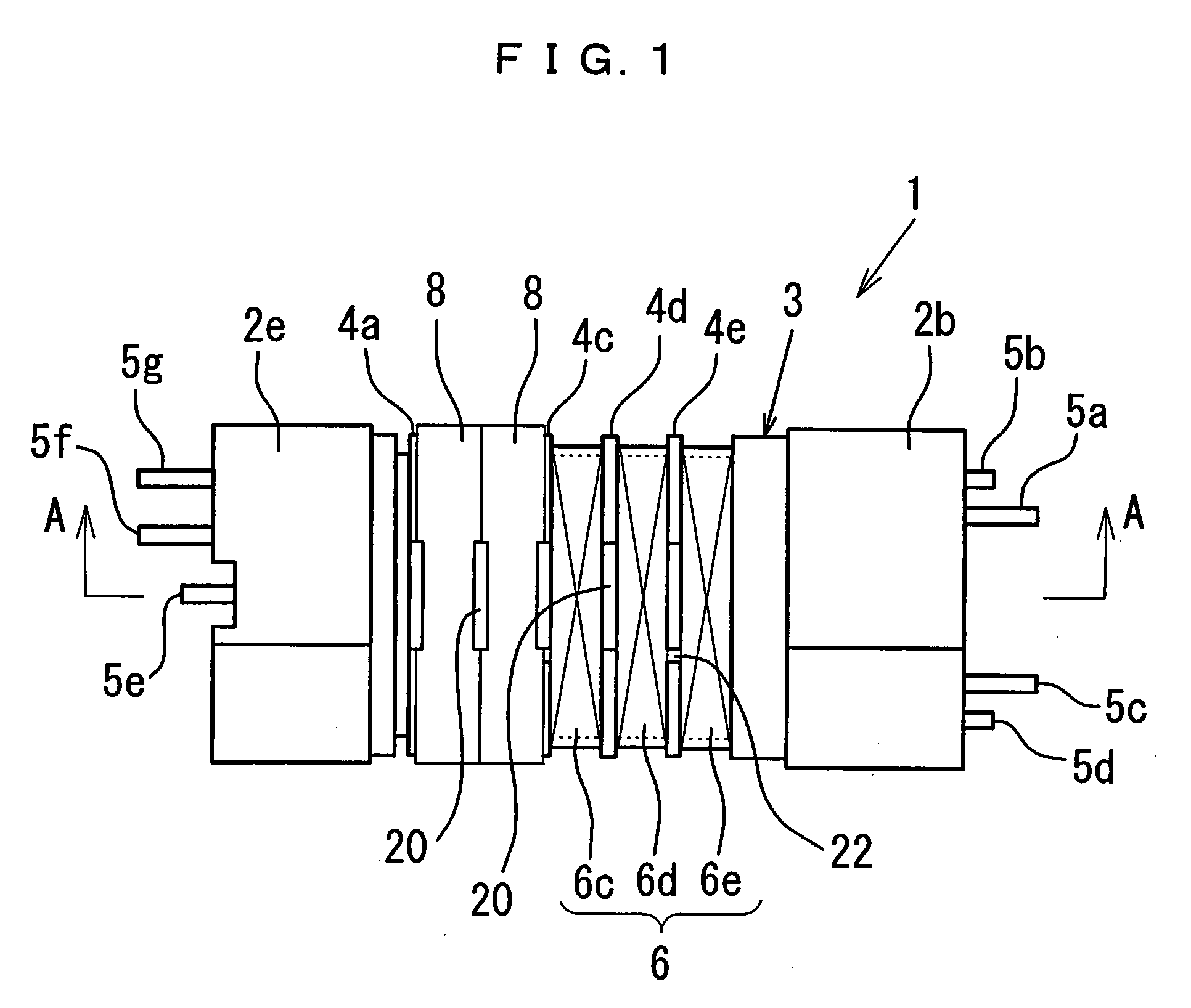
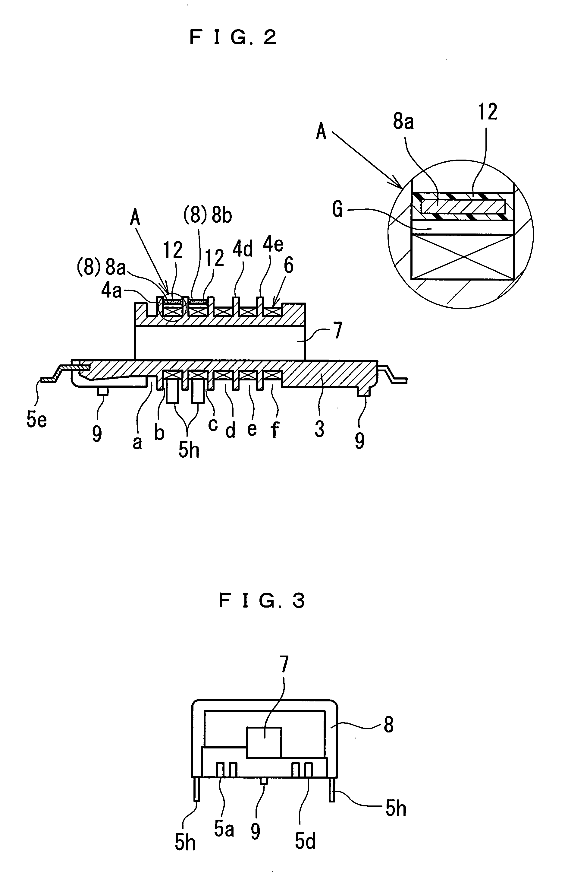
[0028] Referring to FIGS. 1 and 2, a high voltage transformer according to an embodiment of the present invention includes a bobbin 1 which is formed of resin, such as liquid crystal polymer (LCP), and which integrally includes a spool body 3 and two terminal blocks 2a and 2b located at the respective ends of the spool body 3, and one terminal block 2a thereof is provided with terminals 5a, 5b, 5c and 5d while the other terminal block 2b is provided with terminals 5e, 5g and 5f.

[0029] The spool body 3 is partitioned by a plurality of flanges 4a to 4e into a plurality (six in FIGS. 1 and 2) of sections a to f disposed along the axial direction, and has a primary winding 8 and a secondary winding 6 disposed therearound as shown in FIG. 2. Referring to FIG. 2, each of the flanges 4a to 4e has a projection 20 at its top side (upper side in FIG. 4), and has ...


PUM


Abstract

A high voltage transformer is provided in which a primary winding is located selectively and optimally with respect to a secondary winding, and so the primary winding is allowed to be tightly coupled electromagnetically to the secondary winding, while the workability in assembly is improved. In the high voltage transformer, a primary winding (8) and a secondary winding (6) are wound around a spool body (3) of a bobbin (1), and a magnetic core made of magnetic material is inserted in the hollow of the bobbin (1). The bobbin (1) includes terminal blocks (2a and 2b) disposed at the both ends of the spool body (3) and provided with a plurality of terminals (5a to 5g), the secondary winding (6) is wound on the outer circumferential surface of the spool body (3), and the primary winding (8) which is constituted by thin conductive sheet coils coated with resin is disposed around the secondary winding (6). A means for fixedly positioning the thin conductive coil sheet constituting the primary winding (8) is formed at the outer circumference of the bobbin (1) or at a board for attaching the bobbin, and the primary winding (8) can be disposed selectively by the positioning means around the secondary winding (6) at the arbitrary and optimal locations thereby modulating the electromagnetic coupling between the primary winding (8) and the secondary winding (6).

Description

BACKGROUND OF THE INVENTION [0001] 1. Field of the Invention [0002] The present invention relates to a high voltage transformer, and particularly to a high voltage transformer for lighting a discharge lamp for use in a liquid crystal display device, and the like. [0003] 2. Description of the Related Art [0004] A discharge lamp, such as a cold cathode lamp and a metal halide lamp, has been used as a light source for a backlight device for a liquid crystal display (LCD) device, a facsimile machine, a copy machine, and like devices. A high voltage is required for lighting such a discharge lamp, and a cold cathode lamp, for example, is lit by an output of an oscillation circuit boosted up to several kV by using a high voltage transformer. Such a high voltage transformer is disclosed in, for example, Japanese Patent Application Laid-Open No. H8-153634. The high voltage transformer disclosed therein includes a magnetic core made of ferrite and inserted in a bobbin which has its spool area...

Claims


Application Information

Patent Timeline
IPC IPC(8): H01F27/30
CPCH01F27/326H01F38/42H01F38/10H01F27/327
Inventor SHINMEN, HIROSHISUZUKI, MITSUAKIWEGER, ROBERT
Owner MINEBEA CO LTD
Why Eureka
Try Eureka