Dynamic motion contrast and transverse flow estimation using optical coherence tomography

Active Publication Date: 2008-01-31
CALIFORNIA INST OF TECH +1
View PDF4 Cites 64 Cited by
  • Summary
  • Abstract
  • Description
  • Claims
  • Application Information

AI Technical Summary

Benefits of technology

[0012] The acquisition methods described herein demonstrate a low efficiency, highly informative diagnostic acquisition as well as an efficient, three-dimensional screening acquisition. The highly efficient acquisition allows for three-dimensional visualization of mobile regions such as a vascular region within t

Problems solved by technology

Phase noise in the system based on the local signal to noise ratio determines the minimum axial flow measurement, which limits the visualization of flow in cases where v or cosθ is very small.
The limited statistics and the short time between the A-scans (and also the phase measurements) severely limit the minimum observable axial flow, allowing for only visualization of the fastest flows.
This lack of additional contrast is because the phase error due to the local signal to nois

Method used


Image

  • Dynamic motion contrast and transverse flow estimation using optical coherence tomography
  • Dynamic motion contrast and transverse flow estimation using optical coherence tomography
  • Dynamic motion contrast and transverse flow estimation using optical coherence tomography

Examples


Embodiment Construction

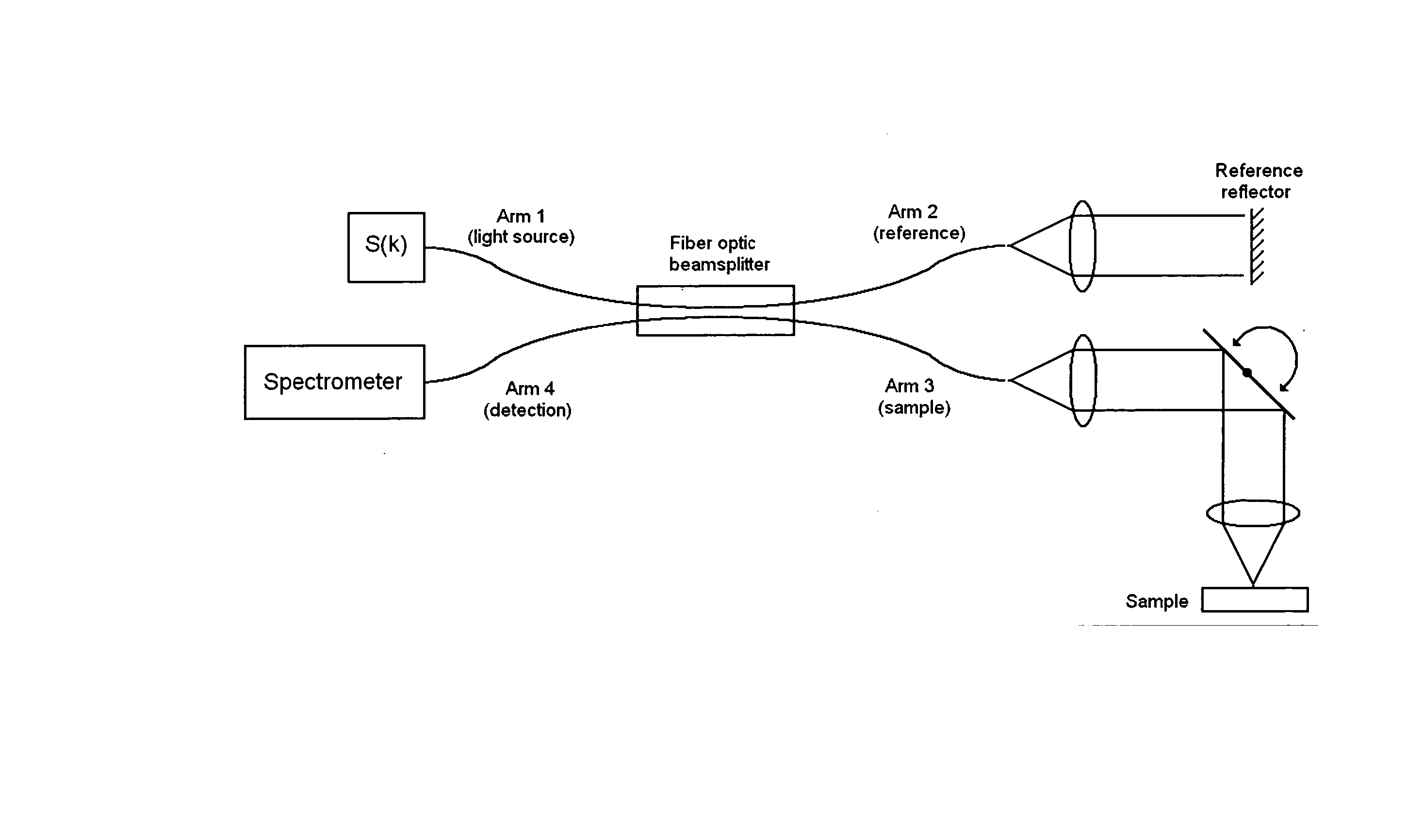
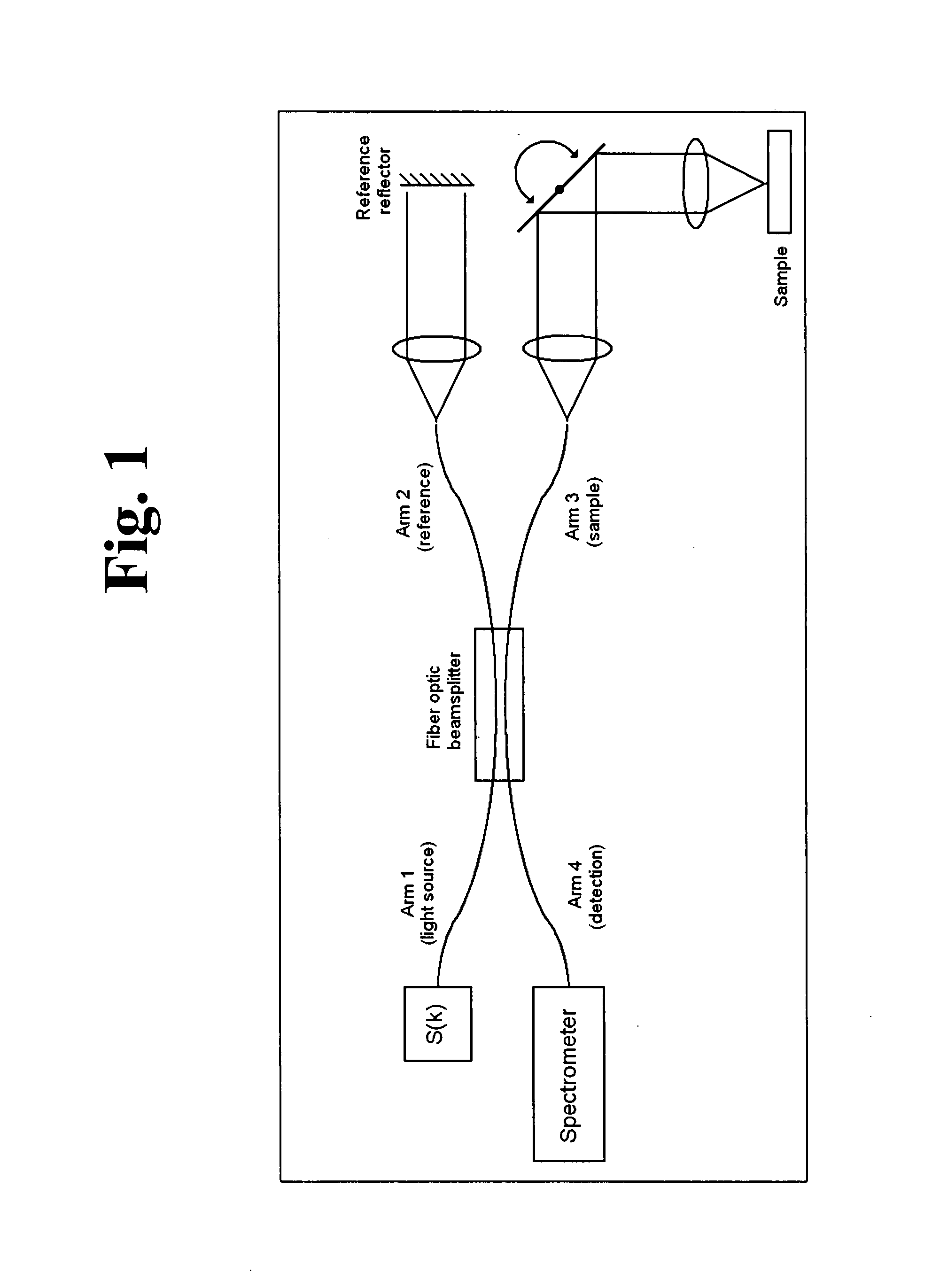
[0015] The OCT system used for the data presented herein is a spectral domain optical coherence tomography (SDOCT) setup as shown in FIG. 1, with a fiber-optic interferometer used to split the light between a reference arm and a sample arm. The acquisition and analysis techniques described herein do not depend on the type of OCT system used, only on the number of intensity and phase samples taken as well as the speed of each depth reflectivity measurement, called an A-scan.

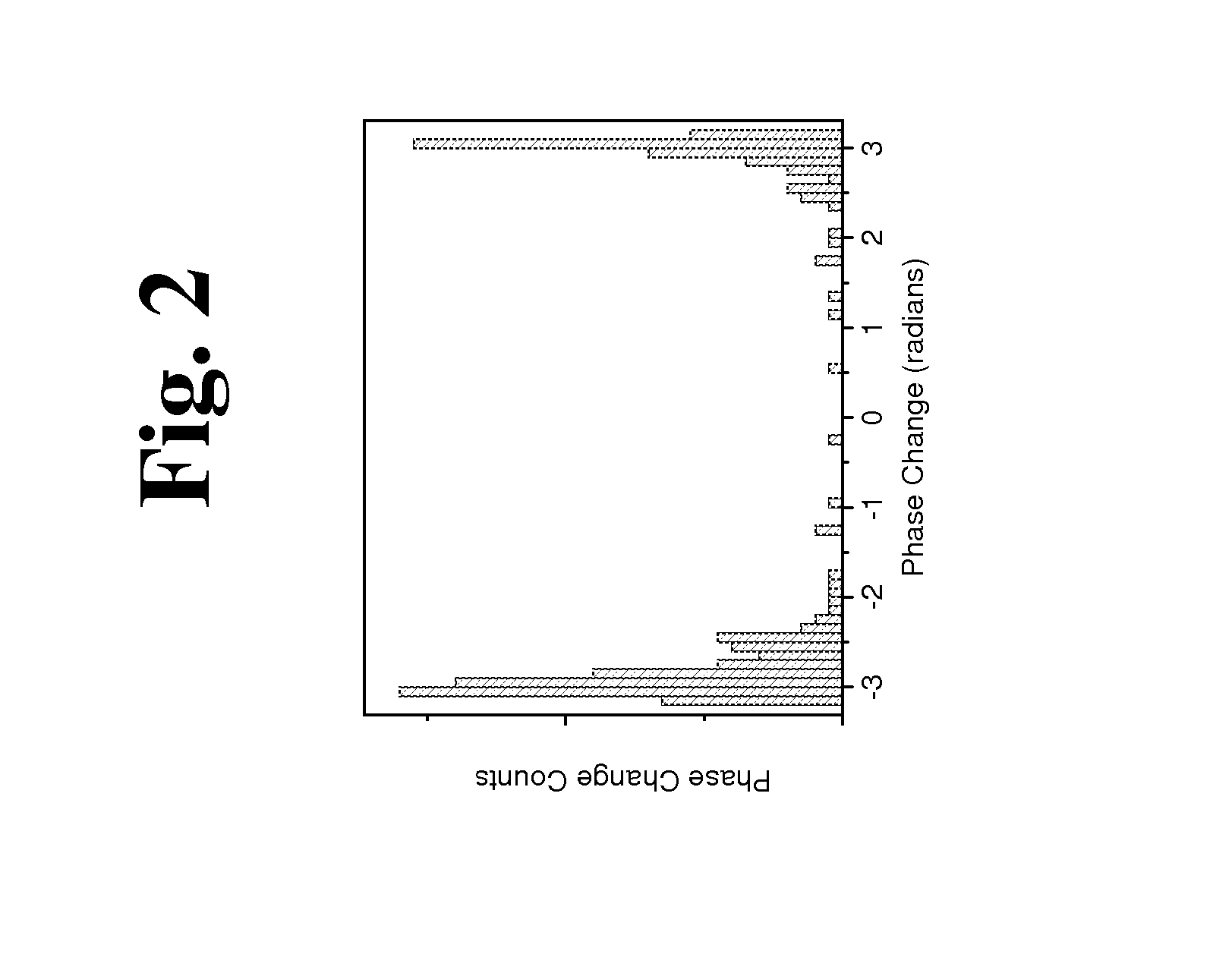
[0016] The phase change Δφ(zi,T) measured for a given depth zi for a time separation T is a combination of several factors effecting the measurement:

Δφ(zi,T)=Δφmotion,scatterer(zi,T)+Δφmotion,bulk(T)+Δφerror,SNR(zi)+Δφerror,other(zi)

[0017] The phase change Δφ(zi,T) contains not only the individual motion of the scatterer at the depth zi which is designated by Δφmotion,scatterer(zi,T) (which is the motion of interest), but it also contains the bulk relative motion between the sample and the system along the imag...


PUM


Abstract

The methods described herein are methods to ascertain motion contrast within optical coherence tomography data based upon phase variance. The phase variance contrast observes the nanometer scale motion of scatterers associated with Brownian motion and other non-flow motion. The inventive method of calculating motion contrast from the phase variance can differentiate regions of different mobility based on the motion contrast differences, and can use the phase information to characterize mobility properties of the scatterers. In flow regions, the inventive method for acquiring and analyzing motion contrast can identify the regions as well as characterize the motion. Furthermore, the inventive method can determine quantitative flow estimation, the index of refraction variations, and absorption variations within flow regions.

Description

CROSS-REFERENCE TO RELATED APPLICATIONS [0001] This application claims the benefit under 35 U.S.C. §119(e) of U.S. Provisional Application Nos. 60 / 816,431, filed on Jun. 26, 2006, and 60 / 853,684, filed on Oct. 23, 2006, each of which is incorporated herein by reference.FIELD OF THE INVENTION [0002] Optical coherence tomography (OCT) is an optical imaging technique that allows for three dimensional visualization and analysis of structures in a variety of biological systems that are difficult to examine and analyze with other imaging techniques. The embodiments of this invention describe methods to produce motion contrast for a variety of motion types in an OCT system by acquiring and analyzing data according to the inventive method based on phase variance and / or intensity fluctuation analysis. BACKGROUND OF THE INVENTION [0003] OCT is a non-invasive optical imaging technique which produces depth-resolved reflectance imaging of samples through the use of a low coherence interferometer...

Claims


Application Information

Patent Timeline
IPC IPC(8): G06K9/00
CPCA61B3/102A61B5/0066G01N2021/1787G01N21/4795A61B5/0261
Inventor FINGLER, JEFFREY P.FRASER, SCOTT E.SCHWARTZ, DANIEL
Owner CALIFORNIA INST OF TECH
Why Eureka
Try Eureka