Optical differential phase shift keying receivers with multi-symbol decision feedback-based electro-optic front-end processing

a technology of optical receivers and feedback loops, applied in electromagnetic receivers, electrical equipment, electromagnetic transmission, etc., can solve the problem of hard optically implementing such solutions, and achieve the effect of reducing errors, easy locking, and increasing sensitivity

Inactive Publication Date: 2008-01-31
TECHNION RES & DEV FOUND LTD
View PDF0 Cites 56 Cited by
  • Summary
  • Abstract
  • Description
  • Claims
  • Application Information

AI Technical Summary

Benefits of technology

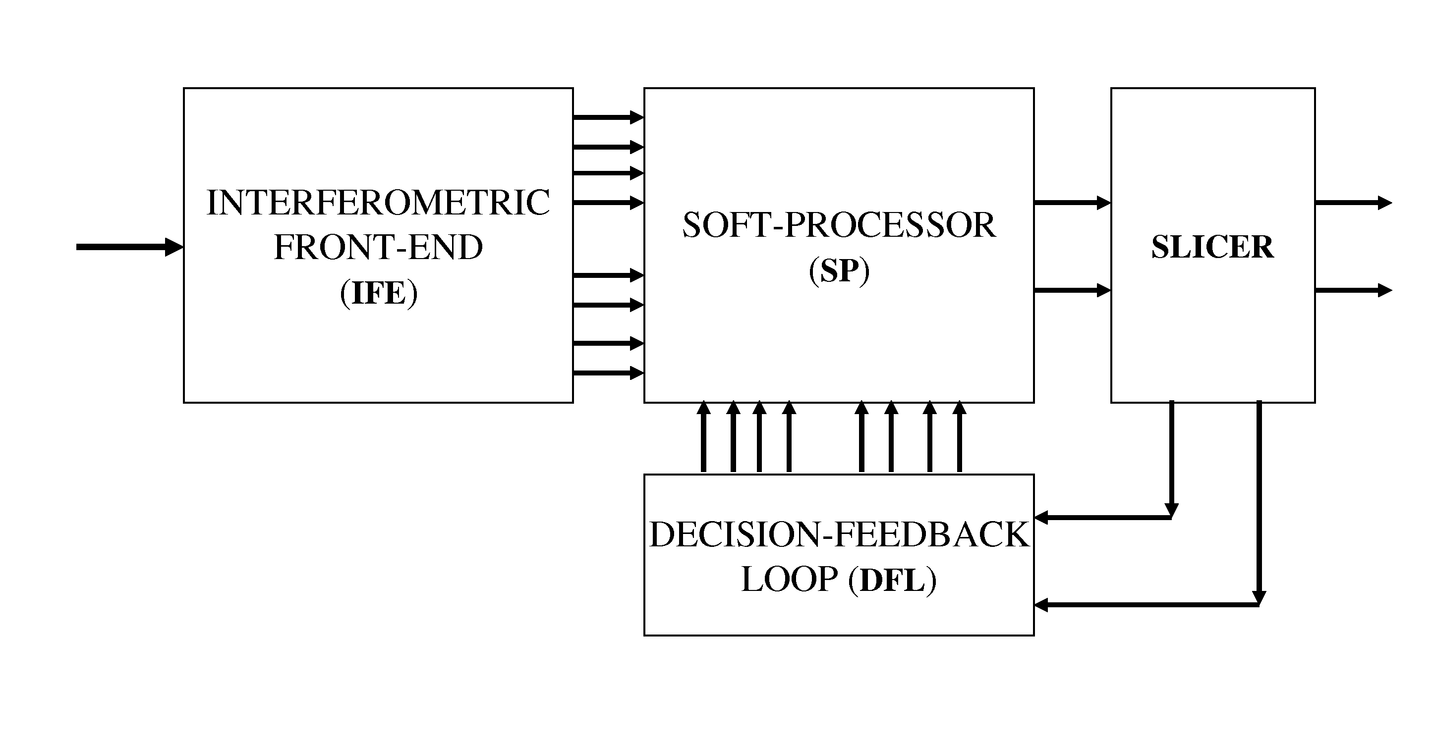
[0053] It is an aspect of the current invention to provide devices, methods and system using “self coherent detection” for detection of optical phase modulated signal. The optical signal itself, delayed at multiple units of the basic bit duration is used instead of locking a “local oscillator” laser to the carrier frequency. In contrast to Radio Frequency (RF) phase Modulation (PM), where local oscillators are commonly used and easily locked using phase locked loop, it is hard to optically implement such solution. The current invention provides increased sensitivity and reduction in errors by utilizing information in the signals at times removed from the currently detected bit by more than one bit duration.

Problems solved by technology

In contrast to Radio Frequency (RF) phase Modulation (PM), where local oscillators are commonly used and easily locked using phase locked loop, it is hard to optically implement such solution.

Method used


Image

  • Optical differential phase shift keying receivers with multi-symbol decision feedback-based electro-optic front-end processing
  • Optical differential phase shift keying receivers with multi-symbol decision feedback-based electro-optic front-end processing
  • Optical differential phase shift keying receivers with multi-symbol decision feedback-based electro-optic front-end processing

Examples


Embodiment Construction

[0154] Before explaining at least one embodiment of the invention in detail, it is to be understood that the invention is not limited in its application to the details of construction and the arrangement of the components set fourth in the following description or illustrated in the drawings. The invention is capable of other embodiments or of being practiced or carried out in various ways. Also, it is to be understood that the phraseology and terminology employed herein is for the purpose of description and should not be regarded as limiting.

[0155] In discussion of the various figures described herein below, like numbers refer to like parts.

[0156] The drawings are generally not to scale.

[0157] For clarity, non-essential elements were omitted from some of the drawings.

[0158] In accordance with the invention, differential phase shift keying optical transmission systems of improved performance are taught. (Multi)Point to (Multi)point and / or wavelength-division multiplexed embodime...


PUM


Abstract

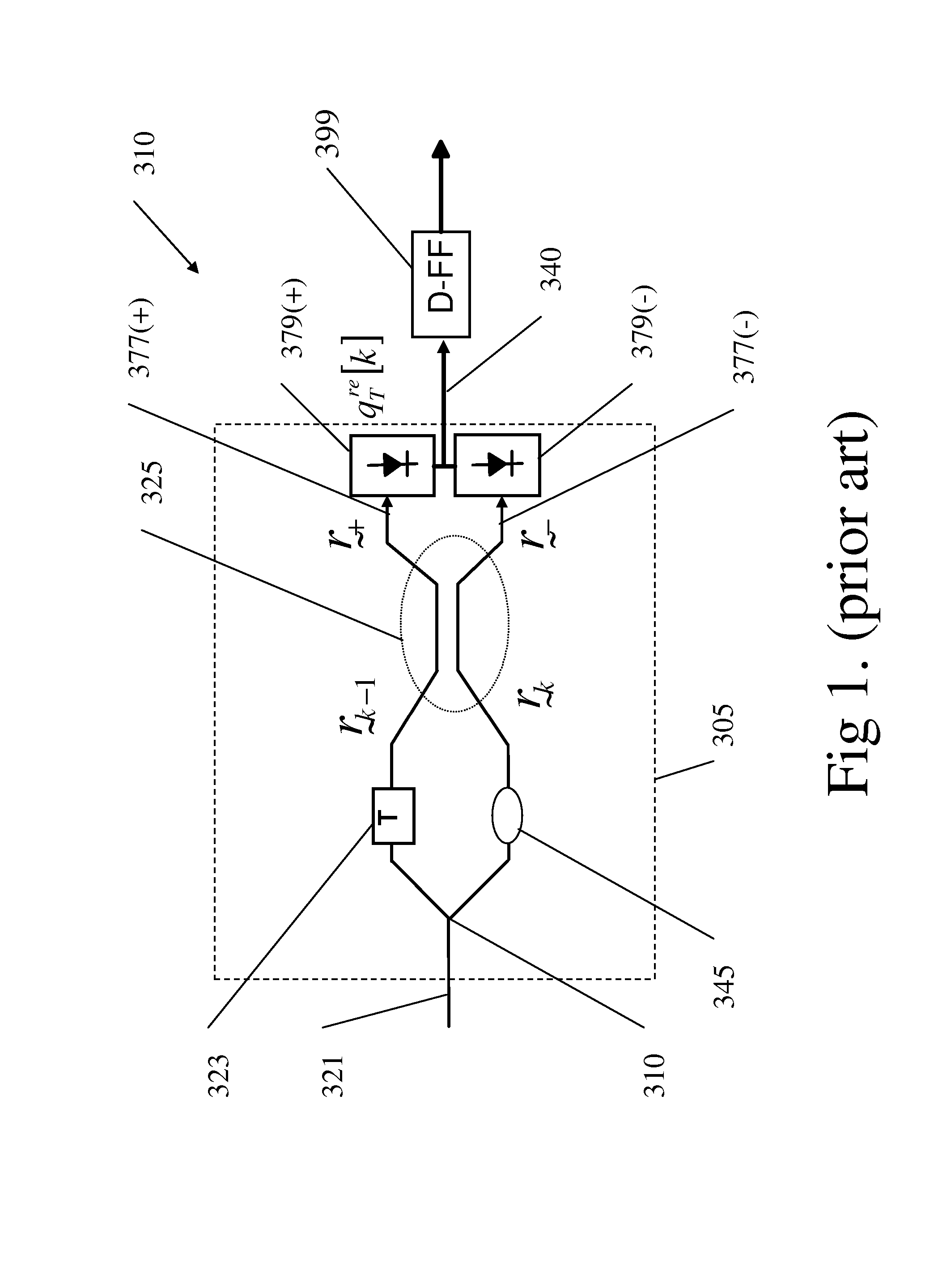
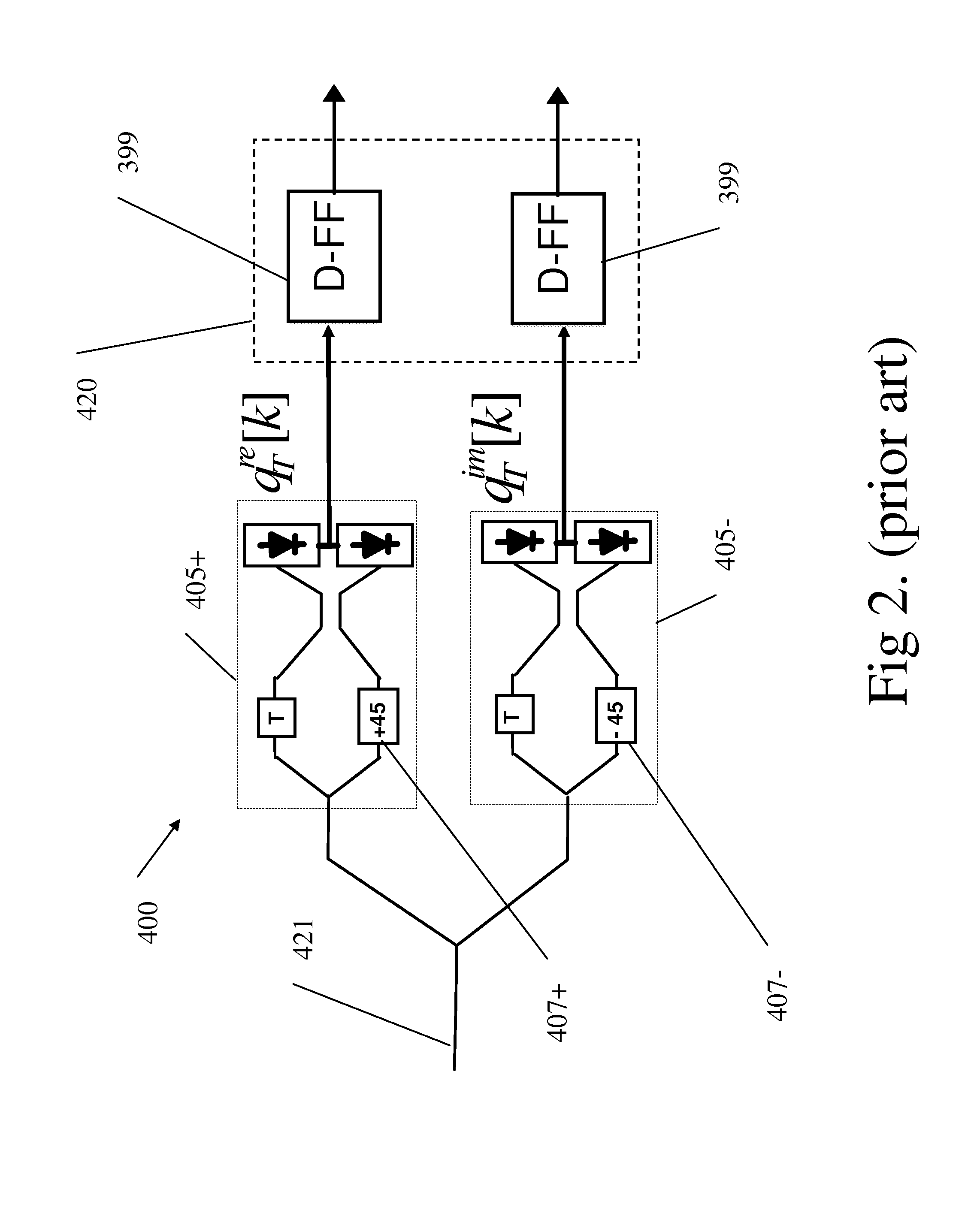
Novel differential-phase shift keying optical receivers are taught based on multi-symbol differential phase shift keying detection (DPSK) aided by decision feedback (DF) from the decision bits in earlier symbol intervals. In accordance with the invention, the DF is directed to an optical front-end comprising multiple Delay Interferometers (DIs) with multiple delays T, 2T, . . . , where T is the DPSK symbol duration. In one embodiment, the DF bitstream is applied to electronically switch the polarity of DI outputs prior to additive combination and hard detection. In other embodiments the DF is applied to active phase-shifting electrodes incorporated in the DIs. In additional embodiments the DF is applied to modified DI devices which not of the conventional Mach-Zehnder asymmetric two-arms type, but rather comprise either three or more arms with appropriate couplings, or two arms, one of which comprises a recirculating delay line with delay T. These embodiments comprise pairs of active phase-shifting electrodes to be activated by the DF. In other embodiments the teachings of this invention for DPSK with DF are combined with the amplitude-shift keying (ASK) modulation format, yielding improved Differential Phase Amplitude Shift Keying (DPASK) systems with decision feedback. The resulting receiver structures exhibit improved performance trade-offs between error-rate, transmission distance and bitrate, compared with conventional DPSK systems, yet are simpler to realize than prior art multi-symbol and / or DF-aided optical DPSK systems.

Description

FIELD OF THE INVENTION [0001] The present invention relates to differential-phase shift keying optical receivers based on multi-symbol differential phase shift keying detection (DPSK) aided by decision feedback (DF) from the decision bits in earlier symbol intervals using optical front-end comprising multiple Delay Interferometers (DIs) with multiple delays. BACKGROUND OF THE INVENTION [0002] The Differential Phase Shift Keying (DPSK) optical modulation format has recently emerged as the highest performance scheme for long-haul ultra-high bit-rate transmission. [0003] The review paper [1] presents a tutorial review of the optical DPSK modulation format. [0004] While not widely deployed yet, it is inevitable that the next generation of ultra high capacity, long-haul optical links will be predominantly DPSK-based, in conjunction with Wavelength Division Multiplexing (WDM). [0005] The DPSK signaling format is widespread in electronic wireless communication. The technology and its advan...

Claims


Application Information

Patent Timeline
Patent Type & Authority Applications(United States)
IPC IPC(8): H04B10/06
CPCH04B10/677
Inventor NAZARATHY, MOSHEYADIN, YOAV
Owner TECHNION RES & DEV FOUND LTD
Why Eureka
Try Eureka