Injection molding machine

a molding machine and injection molding technology, applied in the field of injection molding machines, can solve the problems that the requirements cannot be satisfied by hydraulic systems, and achieve the effects of high rotation speed, increased rotation speed, and quiet operation

Inactive Publication Date: 2008-01-31
DEMAG ERGOTECH GMBH
View PDF19 Cites 19 Cited by
  • Summary
  • Abstract
  • Description
  • Claims
  • Application Information

AI Technical Summary

Benefits of technology

[0025] In order to obtain optimum results for high-speed applications, the second direct drive can be best suited to the requirements at hand. For example, according to another feature of the present invention, the second direct drive may be constructed to operate at increased rotation speed, e.g. in a range of above 750 revolutions per minute and above. Despite these high rotation speeds, the clamping unit of the injection molding machine according to the present invention can still run quietly and with low maintenance needs because of the use of a direct drive, and in addition, has a compact structure and slight dry cycle times as a result of the high accelerations and maximum speeds.
[0026] An injection molding machine according to the prese

Problems solved by technology

These requirements cannot be satisfied by hydraulic systems,

Method used


Image

  • Injection molding machine
  • Injection molding machine

Examples


Embodiment Construction

[0028] The depicted embodiment is to be understood as illustrative of the invention and not as limiting in any way. It should also be understood that the drawing is not necessarily to scale and that embodiments are sometimes illustrated by graphic symbols, phantom lines, diagrammatic representations and fragmentary views. In certain instances, details which are not necessary for an understanding of the present invention or which render other details difficult to perceive may have been omitted.

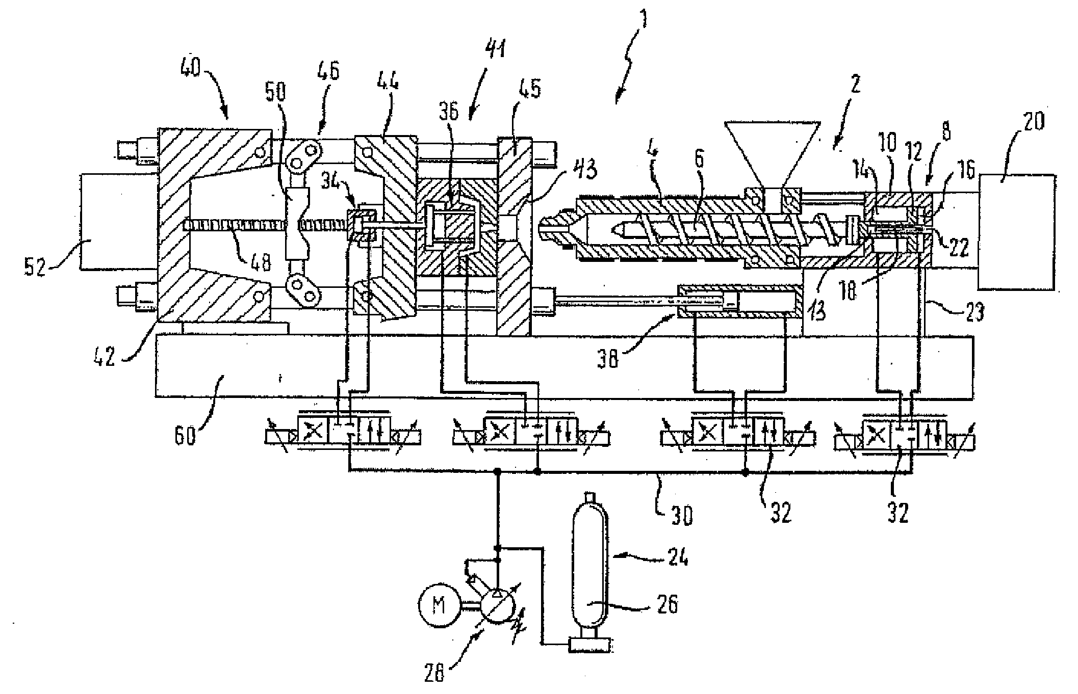
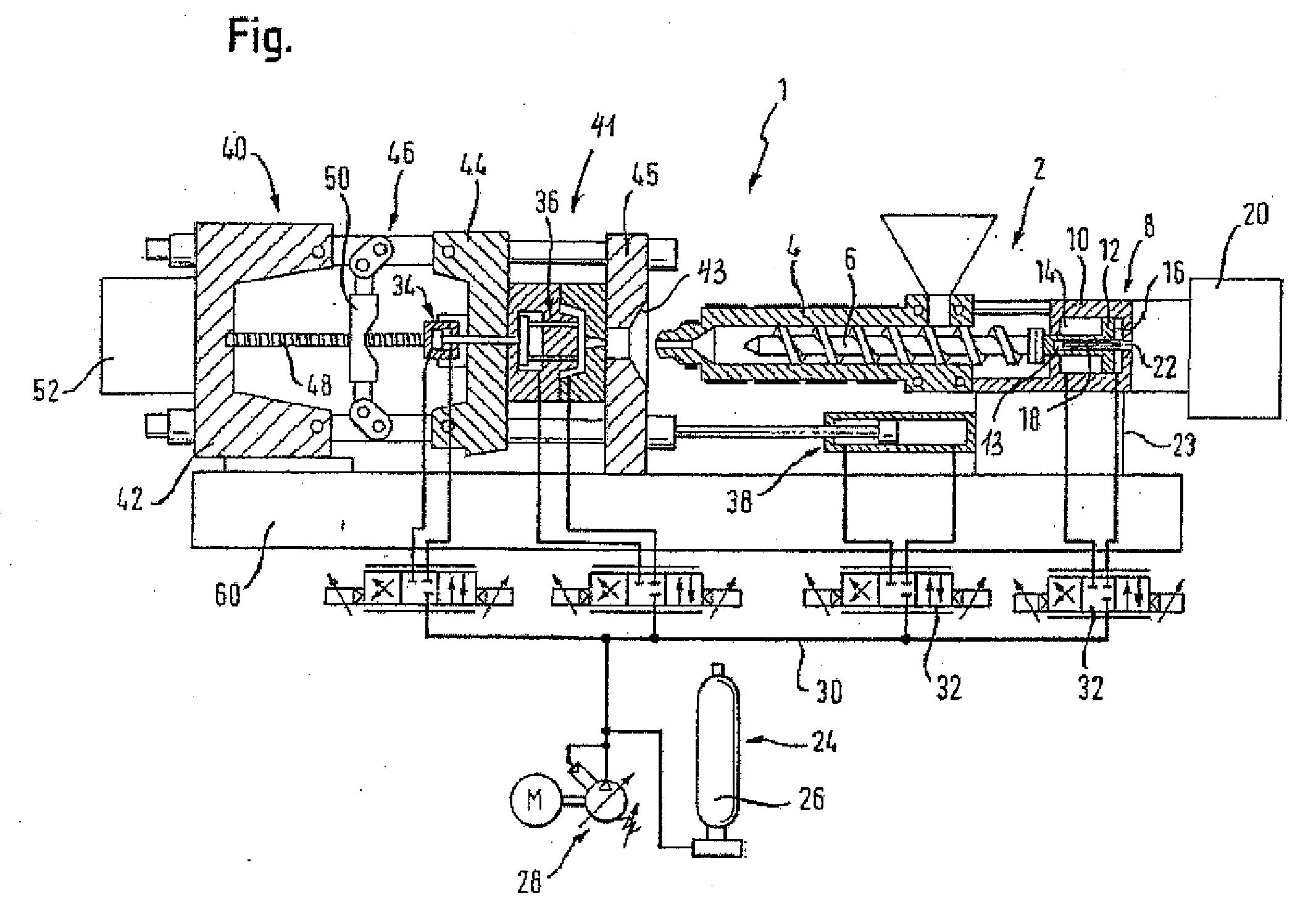
[0029] Turning now to FIG. 1, there is shown a schematic sectional view of an injection molding machine according to the present invention, generally designated by reference numeral 1. The injection molding machine includes an injection unit which is generally designated by reference numeral 2, and a clamping unit, which is generally designated by reference numeral 40. The injection unit 2 has a plasticizing unit with a barrel 4 and a plasticizing screw 6, which is received in the barrel 4 for...


PUM

PropertyMeasurementUnit
Lengthaaaaaaaaaa
Lengthaaaaaaaaaa
Speedaaaaaaaaaa

Abstract

An injection molding machine includes an injection unit and a clamping unit. The injection unit includes a barrel and a plasticizing screw which is supported in the barrel for rotation and movement in axial direction. A first direct drive causes the plasticizing screw to rotate in order to plasticize thermoplastic material, and a hydraulic drive causes the plasticizing screw to move axially in order to effect an injection stroke. The hydraulic drive includes a hydraulic accumulator system which is comprised of a variable capacity pump in combination with a hydraulic accumulator. The clamping unit includes a toggle mechanism for moving a movable platen in relation to a stationary support platen, a spindle mechanism for operating the toggle mechanism, and a second direct drive for operating the spindle mechanism.

Description

CROSS-REFERENCES TO RELATED APPLICATIONS [0001] This application is a continuation of prior filed copending PCT International application no. PCT / EP2005 / 051801, filed Apr. 22, 2005, which designated the United States and has been published but not in English as International Publication No. WO 2006 / 005638 and on which priority is claimed under 35 U.S.C. §120, and which claims the priority of German Patent Application, Serial No. 10 2004 033 690.3, filed Jul. 9, 2004, pursuant to 35 U.S.C. 119(a)-(d), the contents of which are incorporated herein by reference in its entirety as if fully set forth herein.BACKGROUND OF THE INVENTION [0002] The present invention relates, in general, to an injection molding machine. [0003] Nothing in the following discussion of the state of the art is to be construed as an admission of prior art. [0004] A typical injection molding machine includes an injection unit having a plasticizing screw which is caused to rotate by an electric drive for plasticizin...

Claims


Application Information

Patent Timeline
IPC IPC(8): B29C45/17B29C45/50B29C45/82
CPCB29C45/5008B29C45/82B29C2045/1794B29C2945/76785B29C2945/76083B29C2945/7623B29C2945/76498B29C2045/824
Inventor WESSELY, RALPHKUBEL, ANDREASPOPP, HANS-JURGEN
Owner DEMAG ERGOTECH GMBH
Why Eureka
Try Eureka