Method of reducing contamination by providing a removable polymer protection film during microstructure processing

Inactive Publication Date: 2008-01-31
ALSEPHINA INNOVATIONS INC
View PDF48 Cites 23 Cited by
  • Summary
  • Abstract
  • Description
  • Claims
  • Application Information

AI Technical Summary

Benefits of technology

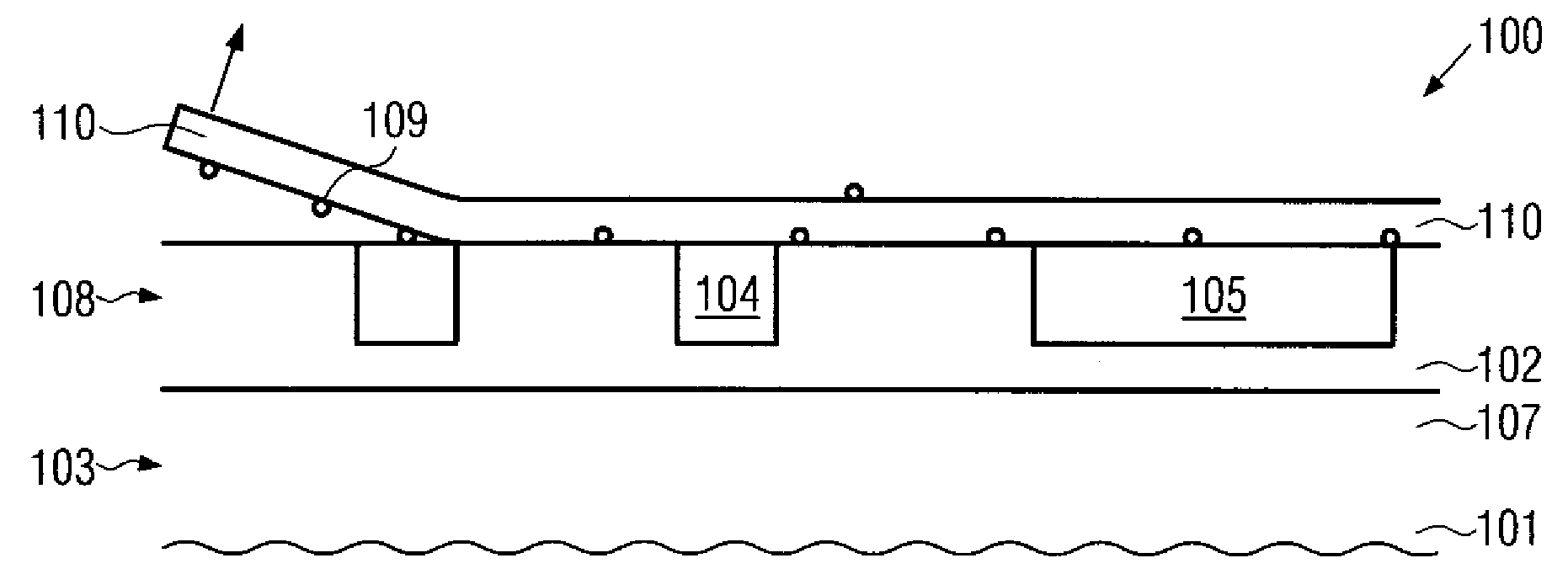
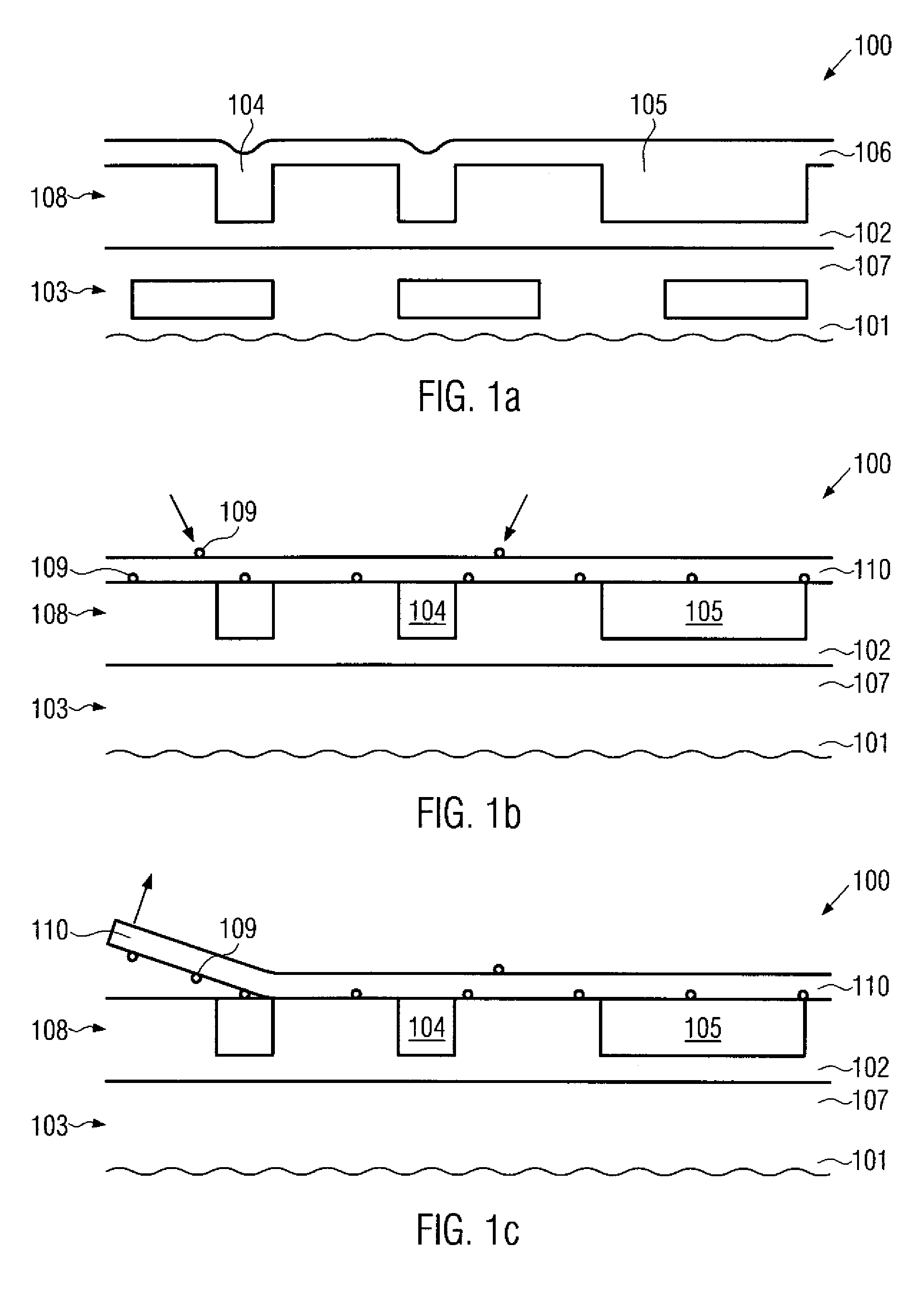
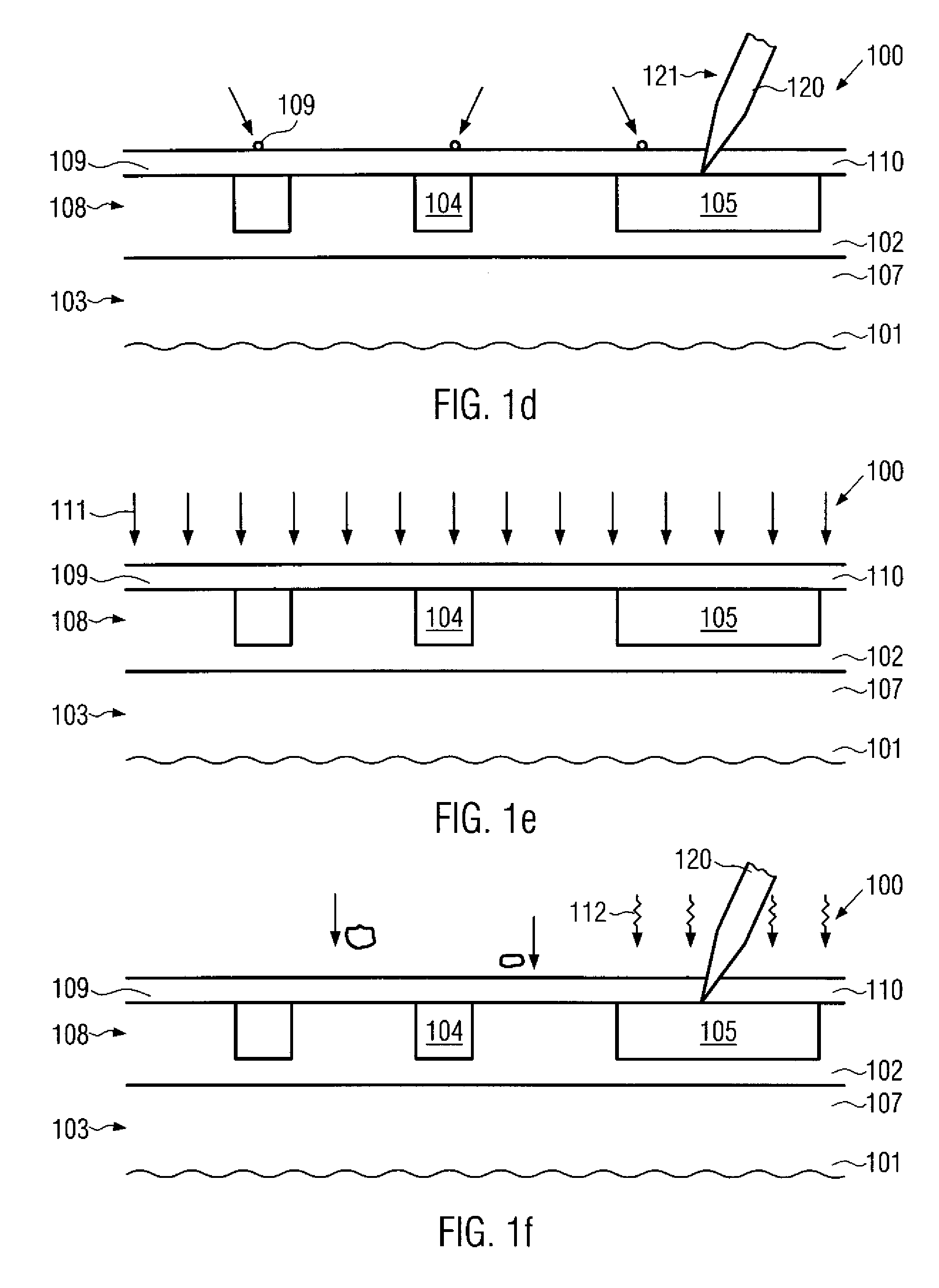
[0009]Generally, the subject matter disclosed herein is directed to a technique for reducing the exposure of sensitive surface areas during the processing of microstructures, such as integrated circuits, in a corresponding facility. For this purpose, at certain manufacturing stages of the microstructure devices, an appropriate protective film or layer may be formed in order to efficiently protect exposed surface areas during further transport activities and/or process and metrology steps. In some illustrative embodiments, the protective film or layer may have a foil-like consistency in order to facilitate the attachment and/or the removal of the protective film prior to and/or after a subsequent process or metrology step, in which surface portions or the entire surface of the subst

Problems solved by technology

Consequently, particle contamination as well as degradation of sensitive exposed surface portions may be significantly reduced by temporarily providing the protective film or layer so as to significantly reduce the influence of varyi

Method used


Image

  • Method of reducing contamination by providing a removable polymer protection film during microstructure processing
  • Method of reducing contamination by providing a removable polymer protection film during microstructure processing
  • Method of reducing contamination by providing a removable polymer protection film during microstructure processing

Examples


Embodiment Construction

[0019]Various illustrative embodiments of the invention are described below. In the interest of clarity, not all features of an actual implementation are described in this specification. It will of course be appreciated that in the development of any such actual embodiment, numerous implementation-specific decisions must be made to achieve the developers' specific goals, such as compliance with system-related and business-related constraints, which will vary from one implementation to another. Moreover, it will be appreciated that such a development effort might be complex and time-consuming, but would nevertheless be a routine undertaking for those of ordinary skill in the art having the benefit of this disclosure.

[0020]The present subject matter will now be described with reference to the attached figures. Various structures, systems and devices are schematically depicted in the drawings for purposes of explanation only and so as to not obscure the present disclosure with details ...


PUM


Abstract

By providing a protective layer in an intermediate manufacturing stage, an increased surface protection with respect to particle contamination and surface corrosion may be achieved. In some illustrative embodiments, the protective layer may be used during an electrical test procedure, in which respective contact portions are contacted through the protective layer, thereby significantly reducing particle contamination during a respective measurement process.

Description

BACKGROUND OF THE INVENTION[0001]1. Field of the Invention[0002]Generally, the present disclosure relates to the field of fabricating microstructure devices, and, more particularly, to techniques for enhancing product yield by reducing the defect rate at several process stages during the formation of complex microstructures, such as integrated circuits and the like.[0003]2. Description of the Related Art[0004]Today's global market forces manufacturers of mass products to offer high quality products at a low price. It is thus important to improve yield and process efficiency to minimize production costs. This holds especially true in the field of fabricating microstructures having a complex configuration, such as advanced integrated circuits, since here it is essential to combine cutting edge technology with mass production techniques. It is, therefore, the goal of manufacturers of microstructures to reduce the consumption of raw materials and consumables while at the same time impro...

Claims


Application Information

Patent Timeline
IPC IPC(8): H01L21/469H01L21/66
CPCH01L21/02074H01L21/02096H01L21/0209
Inventor RICHTER, RALFFEUSTEL, FRANKWERNER, THOMASFROHBERG, KAI
Owner ALSEPHINA INNOVATIONS INC
Why Eureka
Try Eureka