Method and apparatus for applying electronic circuits to curved surfaces

a technology of electronic circuits and curved surfaces, applied in the field of electric or electronic circuits, can solve the problems of virtually impossible precision, and achieve the effect of reducing the cost of precision electric circuit application

Active Publication Date: 2008-02-07
II VI DELAWARE INC
View PDF9 Cites 23 Cited by
  • Summary
  • Abstract
  • Description
  • Claims
  • Application Information

AI Technical Summary

Benefits of technology

[0018]The invention has the further object of reducing the expe

Problems solved by technology

When using the techniques of the prior art, such precision is virtually impossible to achieve when

Method used


Image

  • Method and apparatus for applying electronic circuits to curved surfaces
  • Method and apparatus for applying electronic circuits to curved surfaces
  • Method and apparatus for applying electronic circuits to curved surfaces

Examples


Embodiment Construction

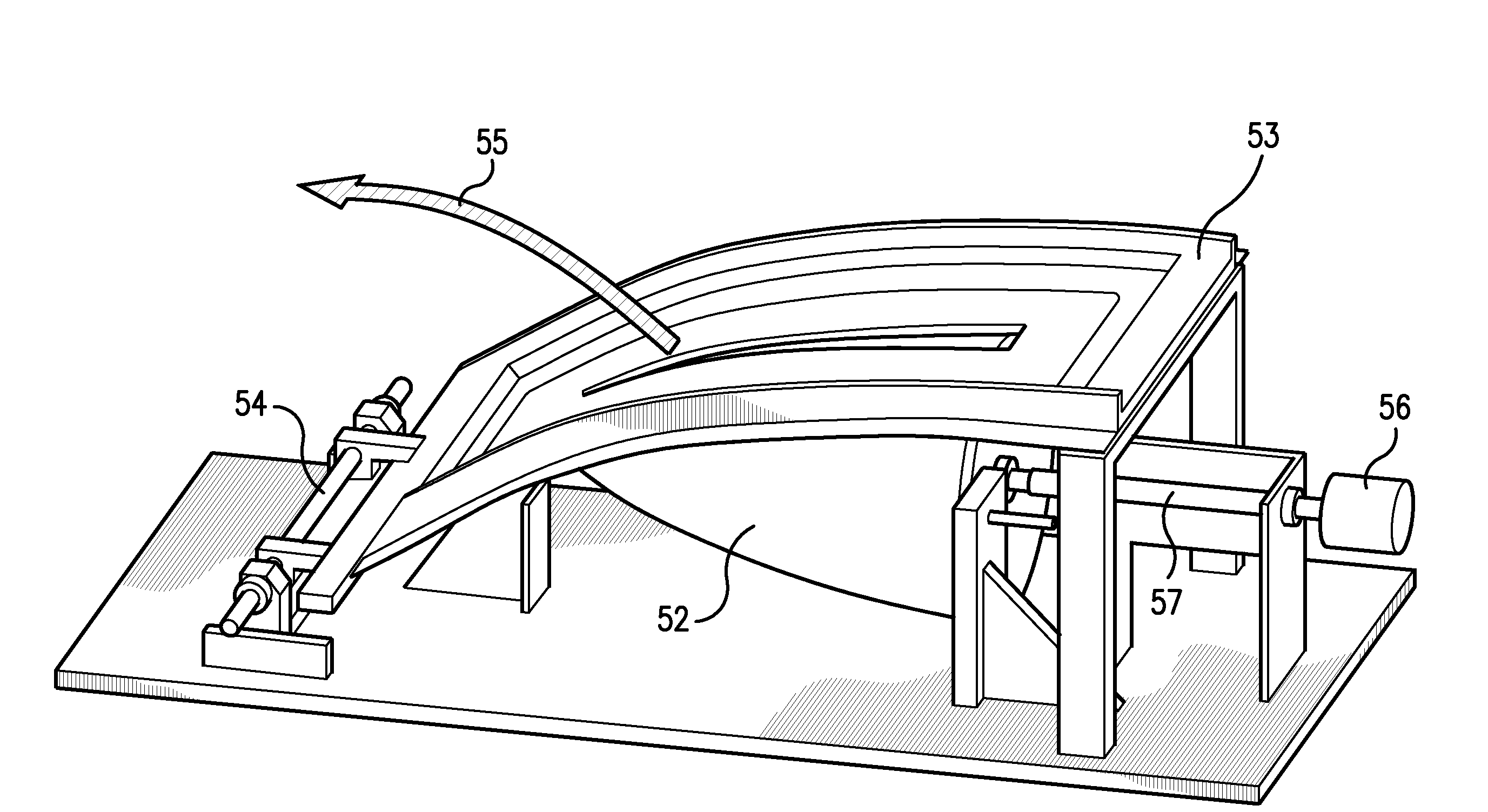
[0028]The present invention includes a method and apparatus for applying electrical circuits to objects having curved surfaces. The circuit is intended for use in rugged environments, and is therefore embedded within a dielectric which is applied to the curved surface.

[0029]In very general terms, the process of the present invention includes preparing the curved surface to insure that it is smooth, applying one or more initial layers of dielectric to the surface, applying conductive cermet defining the desired circuit, and applying one or more final or covering layers of dielectric. The step of applying the conductive cermet is performed for various sections of the surface, each section comprising less than the entirety of the surface.

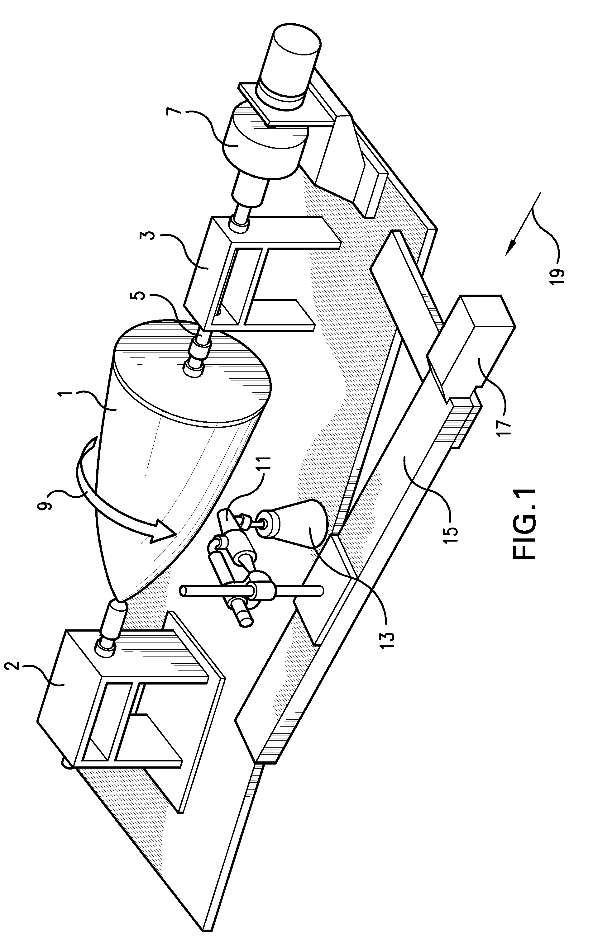
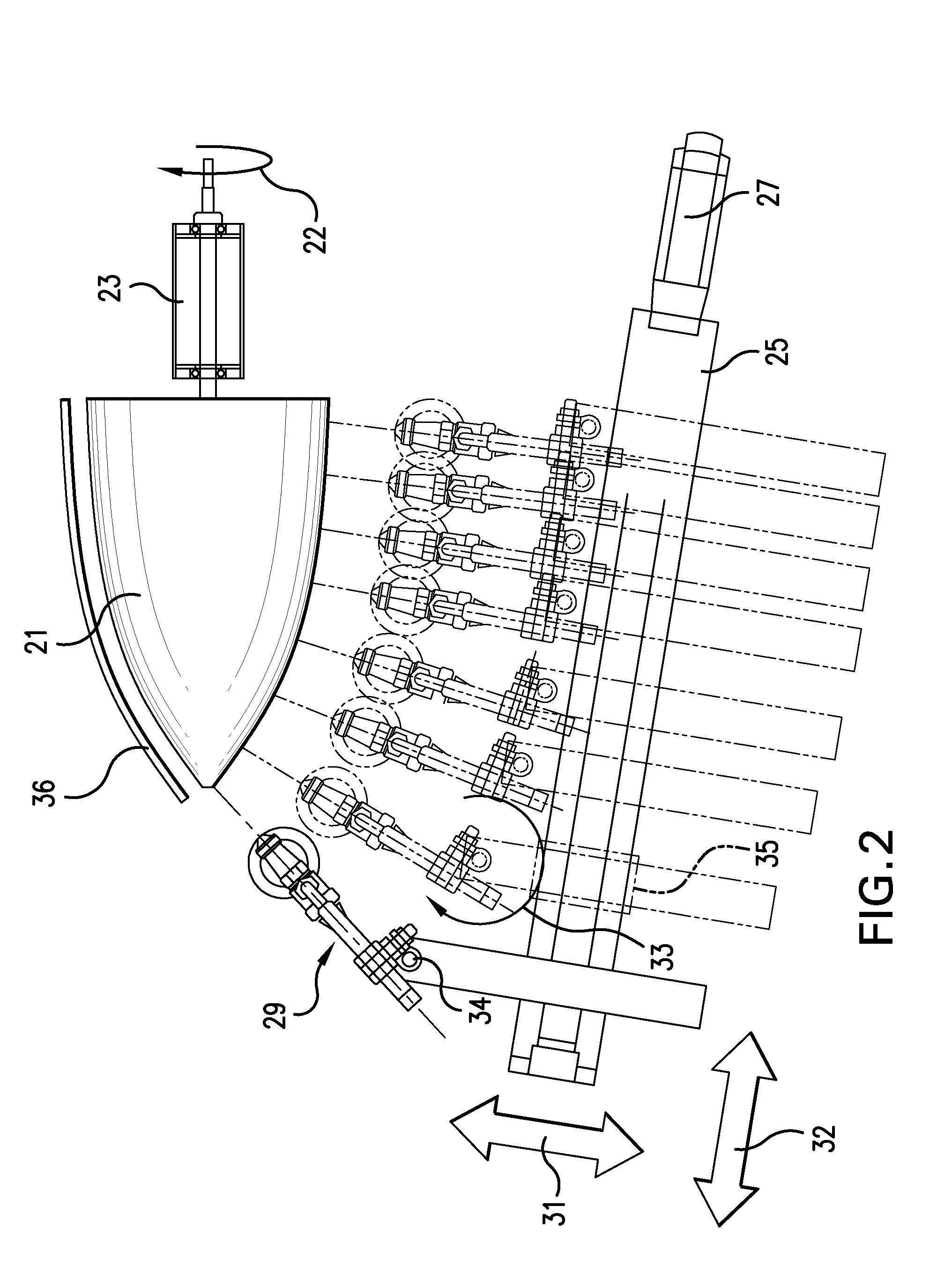
[0030]FIGS. 1-3 illustrate the apparatus for applying the dielectric. FIG. 1 illustrates a simple form of a curved object to which a circuit is to be applied, namely an ogive nose cone 1, mounted for rotation with shaft 5, and supported by supports 2 a...


PUM


Abstract

An electric circuit is applied to an object having a curved surface. The curved surface of the object is divided into sections, and the circuit is applied one section at a time. The circuit is formed between layers of dielectric material. The dielectric is applied by a computer-controlled device, which controls the position of a spray head and the rotation of the object, such that the spray head is held substantially perpendicular to the surface of the object at all times, and such that a controlled thickness of dielectric material can be deposited. The fine-featured circuits formed by the invention are rugged, and can be used on objects intended to be exposed to harsh environments.

Description

BACKGROUND OF THE INVENTION[0001]This invention relates to the field of electric or electronic circuits which are embedded within a dielectric and applied to a curved surface. The invention is especially useful in manufacturing circuits which are intended to operate in harsh environments.[0002]As used herein, the term “circuit” is used in its broadest sense, to include any pattern of electrical conductors which accomplishes some useful object. Such circuits may be active or passive.[0003]One example of the use of the present invention is in the aerospace and defense industries. It may be necessary to provide circuitry as a covering for the nose cone or radome of a missile, or the nose of an aircraft, to act as shield against radio frequency (RF) energy, or as an electromagnetic shield. Certain circuit patterns may be capable of blocking incoming radiation while remaining transparent to radiation transmitted by an internal antenna within the missile or aircraft. The invention is not ...

Claims


Application Information

Patent Timeline
IPC IPC(8): B41M1/12
CPCH01Q1/42H05K1/0284H05K3/0091H05K3/1216H05K2203/1554H05K2201/09018H05K2203/1366H05K2203/1476H05K3/4664
Inventor SEDBERRY, DONALD C.ROLLINS, DEREK S.METZGER, DAVID S.
Owner II VI DELAWARE INC
Why Eureka
Try Eureka