Axial flow cooling for air-cooled engines

a technology of air-cooled engines and fins, which is applied in the direction of engine cooling apparatus, air cooling, cylinders, etc., can solve the problems of increasing pressure, reducing the useful power output of the engine, and the net efficiency of the engine, and orientating the fins perpendicular to the longitudinal axis of the cylinders

Inactive Publication Date: 2008-02-07
CORDY JR CLIFFORD B
View PDF12 Cites 3 Cited by
  • Summary
  • Abstract
  • Description
  • Claims
  • Application Information

AI Technical Summary

Benefits of technology

[0014] In accordance with another aspect of the present disclosure, the foregoing head is structured to have more total fin surface area provided near the exhaust port than near the intake port in the head. In accordance with another aspect of the present inve

Problems solved by technology

In the horizontally opposed air-cooled engines with 4 or more cylinders that are commonly used in automotive and aircraft applications, having the fins oriented perpendicular to the longitudinal axis of the cylinders is a serious disadvantage.
This reduces the useful power output of the engine, and the net efficiency of the engine.
But the restriction at the passage between cylinders always increases the pressure required to force sufficient air thru the engine, and there are unavoidable dead-air regions above and below the cylinder and combustion chamber where very little cooling occurs.
With the air flow passing down between the cylinders, this is unavoidable.
The result is excessive power required for cooling (very undesirable), and the possibility of insufficient cooling under some or all operating conditions (even more undesirable).
It does little good to try to cool the engine from the “top” (farther from the crank shaft).
The rocker arms sit on top of the engine, and that assembly introduces so much thermal impedance that it is impractical to co

Method used


Image

  • Axial flow cooling for air-cooled engines
  • Axial flow cooling for air-cooled engines
  • Axial flow cooling for air-cooled engines

Examples


Embodiment Construction

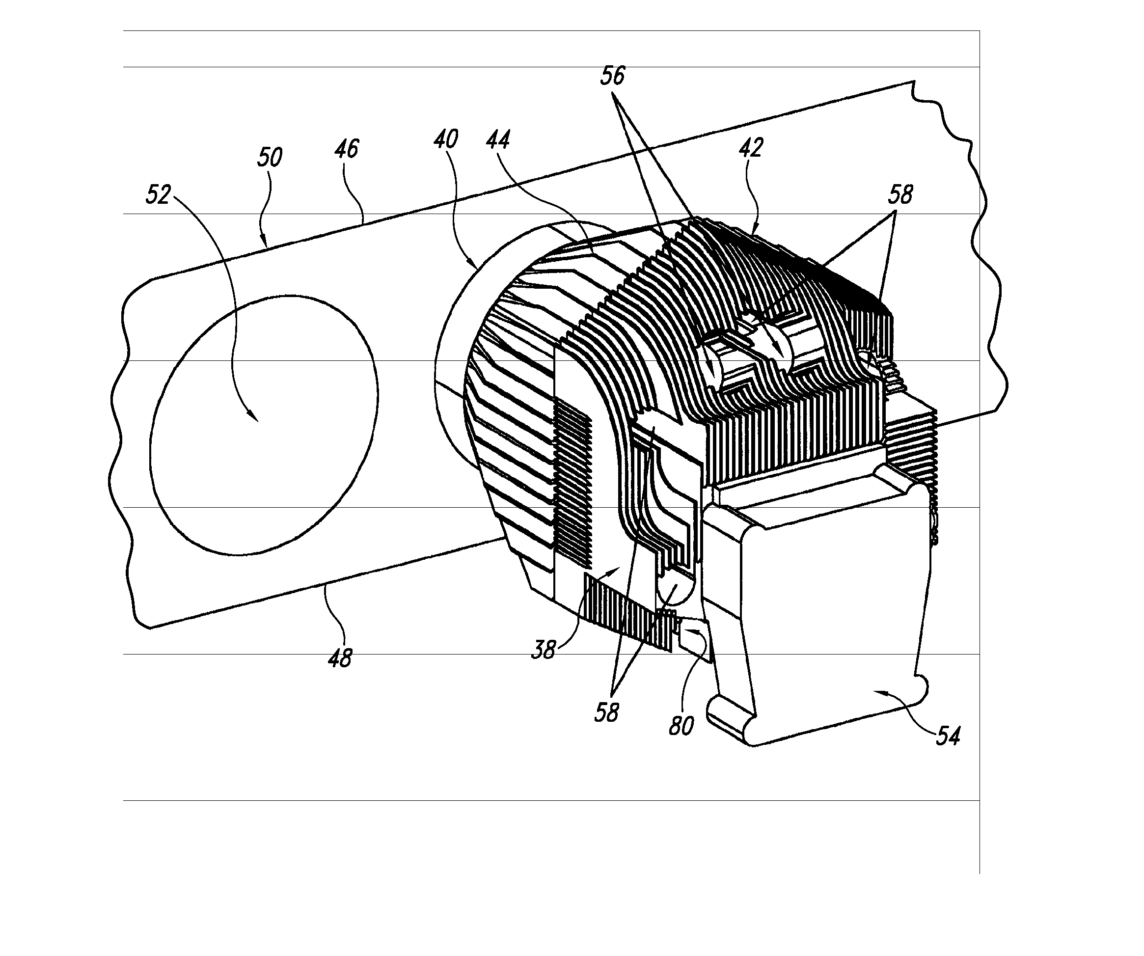
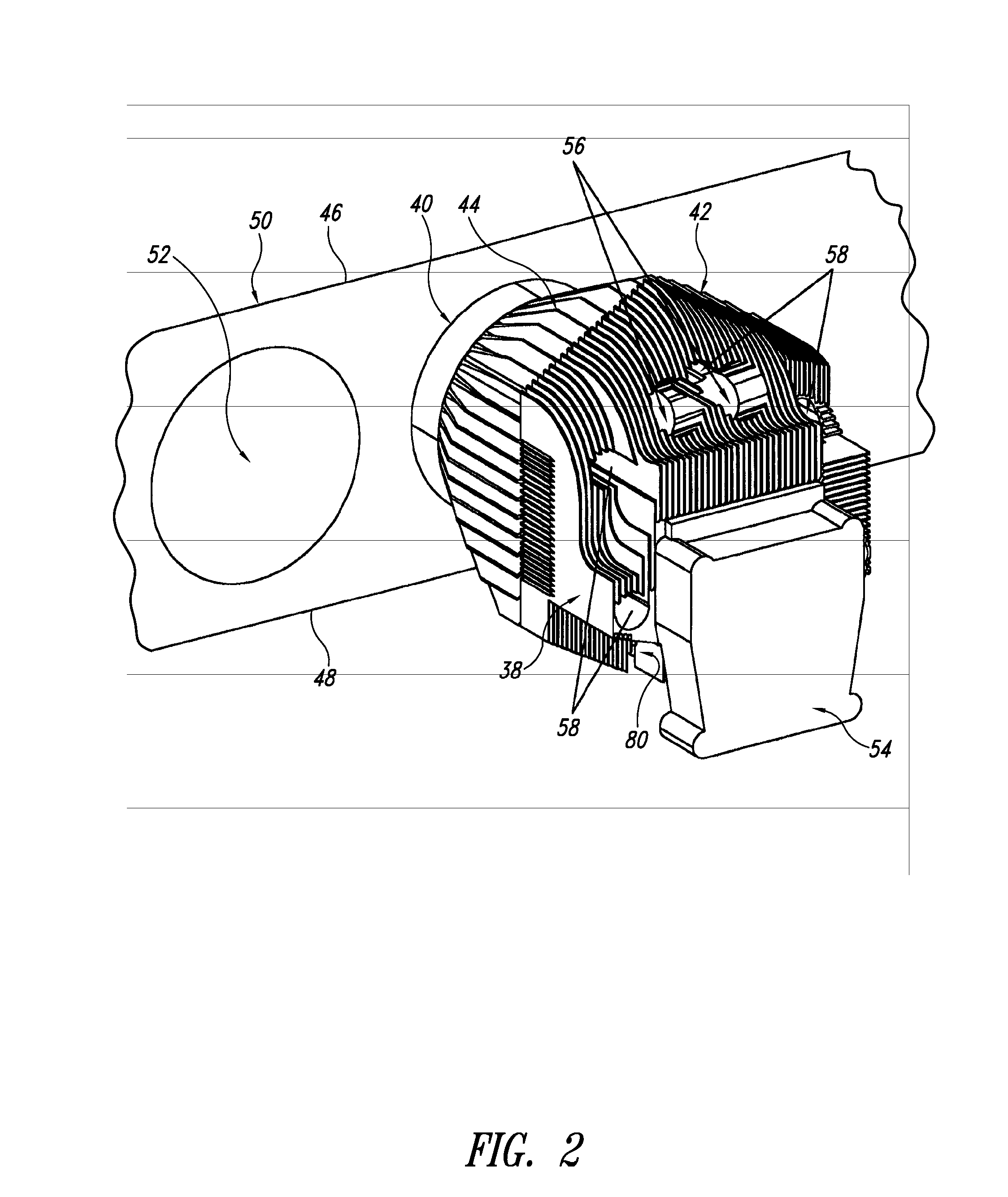
[0032] Most of the problems of both updraft cooling and downdraft cooling are eliminated by a novel cooling configuration disclosed herein, henceforth referred to as axial cooling, with the flow of cooling air traveling substantially parallel to the axis of the cylinder. Fins on the cylinder and head are oriented so they are substantially parallel to the axis of the cylinder. Cooling air is injected into the fin structure near the rocker arms. From there it flows over the head fins, then over the cylinder fins toward the crankcase. Ducts contain the air within the fin structures. The ducts may terminate some distance from the crankcase, allowing the warmed air to escape. Better, the ducts may guide the warmed air toward the cooling air outlet, where it may be accelerated out of the engine compartment using exhaust augmentation. It is not necessary for the fins on the head to be aligned with the fins on the cylinder. In fact, it is undesirable for the two sets of fins to be aligned. ...


PUM


Abstract

A head for an air-cooled engine having at least two cylinders, each cylinder having a longitudinal axis, the head having a rocker arm mounted to rotate about a rocker arm axis in the head, the head further including an intake port and an exhaust port, and the head mounted on a first cylinder of the two cylinders to define a combustion chamber, the head having at least two fins, each fin having a height-to-thickness ratio of greater than or equal to 5, each fin having a length that is at least 5 times the distance between the at least two fins at a location on the head that is between the first cylinder and the rocker arm axis on the head, and each fin positioned on the head with the fin length oriented along an axis that is substantially parallel to the longitudinal axis of the first cylinder.

Description

BACKGROUND OF THE INVENTION [0001] 1. Field of the Invention [0002] The present disclosure pertains to the cooling of internal combustion engines and, more particularly, to a unique fin design for use with air-cooled engines, such as aircraft engines, automobile, truck, and motorcycle engines, and stationary, fan-cooled engines. [0003] 2. Description of the Related Art [0004] In general, air-cooled engines have fins that require the cooling air to flow in a direction perpendicular to the axis of the cylinder. In a single cylinder engine, or an engine with a single bank of cylinders (such as a V2, a horizontally opposed 2, or a single bank radial), this is not a bad configuration. There is adequate space for fins and cooling air. Even a double bank radial works fairly well because the cylinders of the rear bank are oriented between the cylinders in the front bank, so there is adequate access for the cooling air to reach the aft cylinders. In the horizontally opposed air-cooled engine...

Claims


Application Information

Patent Timeline
IPC IPC(8): F02F1/26F01P1/02F02F1/06
CPCF02F1/06F01P1/02
Inventor CORDY, CLIFFORD B. JR.
Owner CORDY JR CLIFFORD B
Why Eureka
Try Eureka