Totally Enclosed Type Main Drive Motor for Vehicle
Inactive Publication Date: 2008-02-07
KK TOSHIBA
View PDF5 Cites 43 Cited by
Summary
Abstract
Description
Claims
Application Information
AI Technical Summary
This helps you quickly interpret patents by identifying the three key elements:
Problems solved by technology
Method used
Benefits of technology
Benefits of technology
[0044] According to the above constitution, when the motor is operated, the cooling air duct absorbs heat and release the heat to the atmosphere through a number of radiator fins. Then, since cooling ambient air during a vehicle's traveling flows along the outer circumferential surface of the cooling air duct, dust and rag mixed into the outside air do not adhere to the cooling air duct and the radiator fins for stagnancy, so that the adhesion of dust can be avoided in spite of a longstanding operation. Additionally, a cleaning operation, such as blowing using compressed air, allows the dust to be removed easily and certainly.
Problems solved by technology
However, with a difficulty that the filter can trap dust perfectly, the dust entering into the motor adheres to its inside for gradual deposition to cause motor's insulating performance and cooling effect to deteriorate.
Thus, the motor is assembled in a limited space with no room.
However, this method causes the price of a vehicle to be increased due to the arrangement of the duct.
Additionally, as the frequency of maintenance / inspection is increased due to the exchange of a filter in a ventilation strainer and the noise radiated to the outside is also increased, the method cannot agree to the request of the times.
Nevertheless, due to the complexity of the pipes 31 intersecting with the radiator fins 32, it is difficult to eliminate the dust etc. adhering to deep portions of the cooler.
Therefore, the circulation movement in the cooler and the motor as a whole deteriorates to cause a reduction in the cooling efficiency of the whole motor.
In a totally enclosed type main drive motor having the conventional piping structure, it is unavoidable that the motor is large-sized because of its inferior cooling efficiency, in comparison with an opened self-ventilation cooler type main drive motor.
Thirdly, due to the structure where the circumferences of the pipes 31 are joined to the radiator fins 32 by welding, an operator has to perform just as many welding operations for the pipes and the radiation fins as there are, causing an inferior commercial production and a rise in manufacturing cost.
Method used
Image
Click on the blue label to locate the original text in one second.
Reading with bidirectional positioning of images and text.
Examples
ninth embodiment
[0154] A totally enclosed type main drive motor of the ninth embodiment for vehicle of the present invention will be described with reference to FIGS. 21 and 22.
[0155] In FIGS. 21 and 22, a cylindrical stator core 20A is attached to an inner circumferential surface of a stator 10. Stator coils 30 are accommodated in a number of grooves formed over the whole circumference of an inner circumferential part of the stator core 20A. A bearing bracket 40 having a bearing 60 built-in and a bearing housing 50 having a bearing 70 built-in are attached to both ends of the stator frame 10 respectively. The bearings 60, 70 supports a rotor shaft 80. A rotor core 90 is attached to a longitudinal center part of the rotor shaft 80. The rotor core 90 is provided, on its outer circumferential part and around the whole circumference, with a number of grooves in which rotor bars 100 are accommodated. On the inner circumferential side of the rotor core 90, a plurality of rotor ventilation holes 90a are ...
embodiment
10th. EMBODIMENT
[0169] Next, a totally enclosed type main drive motor for vehicle in accordance with the tenth embodiment of the present invention will be described with reference to FIGS. 25 and 26.
[0170] According to this embodiment, in view from the axial direction of the motor, a substantially fan-shaped configuration is formed on an extension of blades of the circulating fan 110, by the connective air ducts 210, 220, the cooling air duct 230 and the radiator fins 200 in all.
[0171] In FIGS. 27 and 28, respective currents of the inside wind blown up by the circulating fan 110 (indicated by arrow R) are visually shown with change over time. In the figures, reference numeral 270 designates the distribution of pressures of the wind typically. Due to the circulating fan 110 formed by a centrifugal radial fan, the wind is blown up outwardly in the radial direction by centrifugal forces among the blades and further blown up obliquely in the rotating direction. Therefore, the substant...
second embodiment
[0217] Next, a totally enclosed type main drive motor for vehicle in accordance with the twenty-second embodiment of the present invention will be described with reference to FIG. 59 as a longitudinal sectional view of the motor and FIG. 60 as a front sectional view of the motor.
[0218] In the constitution of the embodiment, the above “inside-air” circulating fan 110 has a main board formed with a curvature radius r, while the arc of the above conductive air ducts 210, 220 and the above cooling air duct 230 is substantially equal to r.
[0219] On the outer circumferential surfaces of the connective air duct 210 and cooling air duct 230, additionally, the radiator fins 200 are formed so that their overall contour is substantially and partially circular in view from the longitudinal direction to the shaft of the motor.
[0220] The operation of the above-constructed totally enclosed type main drive motor for vehicle will be described below.
[0221] The connective air ducts 210, 220 and the...
PUM
Abstract
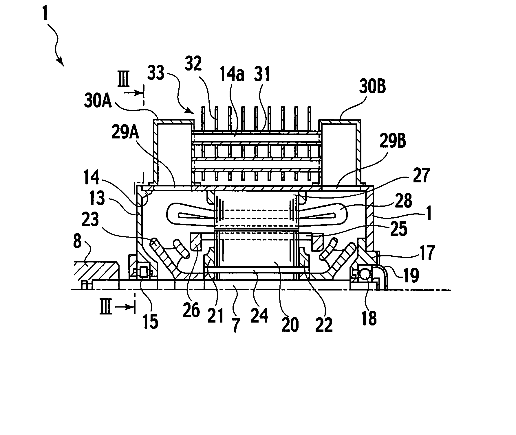
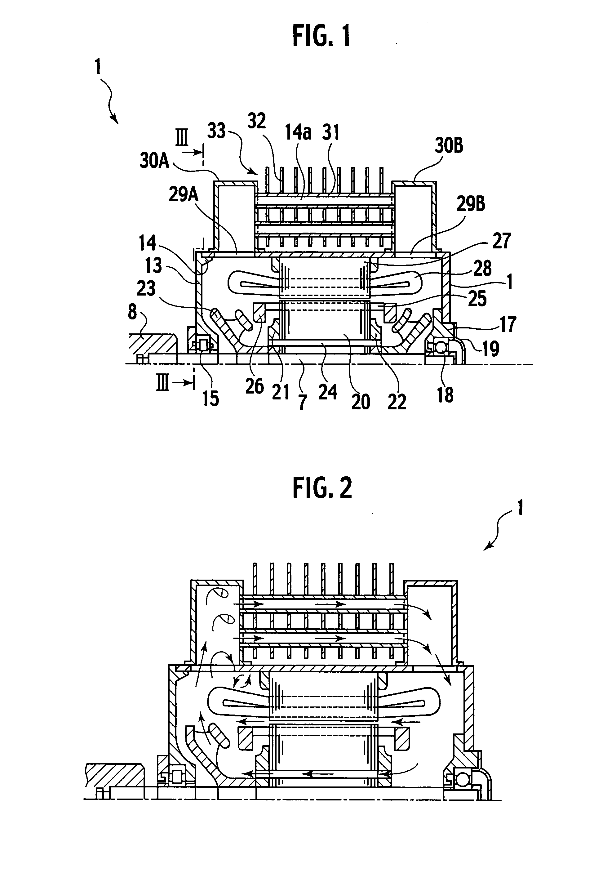
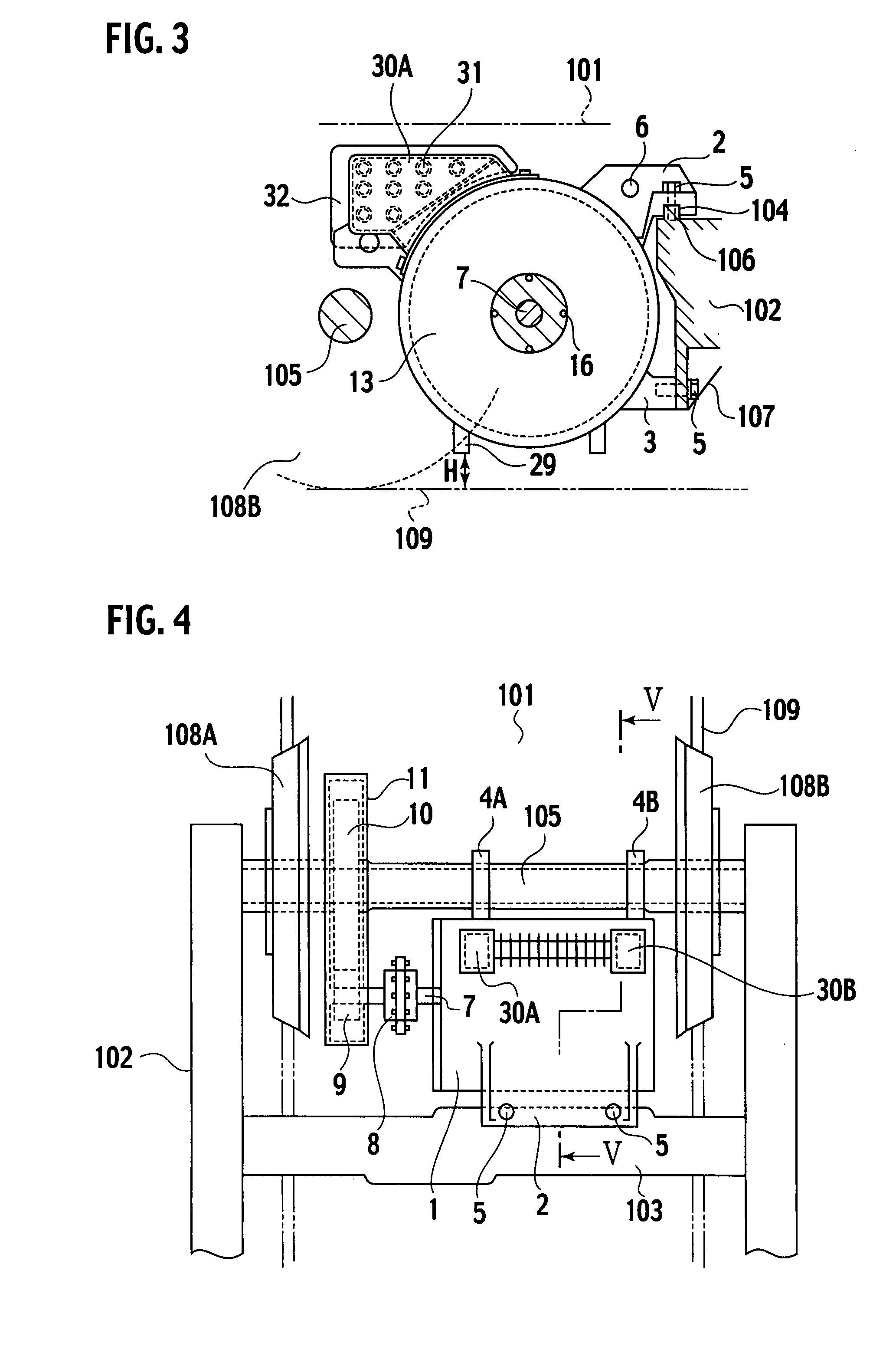
A totally enclosed type main drive motor for a vehicle includes a stator core arranged on an inner circumference of an outer casing frame, a bracket arranged on one end of the outer casing frame to have a bearing built-in, a housing arranged on the other end of the outer casing frame to have a bearing built-in, a rotor shaft having its both ends supported by the respective bearings, a rotor core arranged on the rotor shaft, a fan arranged on one end of the rotor shaft, openings formed in both axial ends of a peripheral wall of the outer casing frame, connective air ducts arranged outside the peripheral wall so as to communicate with the openings and a cooler for connecting these connective air ducts with each other and also releasing heat of air flowing in the connective air ducts to outside air. The outer casing frame is attached to the vehicle so that a central axis of the outer casing frame extends horizontally and intersects with a traveling direction of the vehicle at right angles. With rotation of the fan, air inside the outer casing frame flows in the cooler in circulation to cool down the air. The totally enclosed type main drive motor is provided with guide plates that collect traveling wind flowing around the outer casing frame to the cooler.
Description
TECHNICAL FIELD [0001] The present invention relates to a totally enclosed type drive motor (main motor for driving a vehicle) for driving a railway and particularly, the invention relates to a totally enclosed type drive motor having a totally enclosed structure that does not take outside air into the motor. BACKGROUND OF ART [0002] As the main drive motor for vehicle mounted on a bogie frame (bogie) under a floor of a railway vehicle, an open type main motor (in an open type self-ventilation cooling system) has been adopted conventionally. In the open type main motor, its rotor shaft is provided with a fan rotatable with the rotor shaft. With the rotation of the fan, outside air is sucked into the main motor. Then, the outside air circulates in the main motor and cools down a rotor and a stator. [0003] In this open type self-ventilation cooling system, a ventilation strainer is arranged at an intake part (intake port) of the system in order to prevent an interior of the motor from...
Claims
Application Information
Patent Timeline
Application Date:The date an application was filed.
Publication Date:The date a patent or application was officially published.
First Publication Date:The earliest publication date of a patent with the same application number.
Issue Date:Publication date of the patent grant document.
PCT Entry Date:The Entry date of PCT National Phase.
Estimated Expiry Date:The statutory expiry date of a patent right according to the Patent Law, and it is the longest term of protection that the patent right can achieve without the termination of the patent right due to other reasons(Term extension factor has been taken into account ).
Invalid Date:Actual expiry date is based on effective date or publication date of legal transaction data of invalid patent.

