Distortion compensator and wireless communication device

Inactive Publication Date: 2008-02-07
SONY CORP +1
View PDF6 Cites 9 Cited by
  • Summary
  • Abstract
  • Description
  • Claims
  • Application Information

AI Technical Summary

Benefits of technology

[0016] Accordingly, the present invention, having been completed by addressing the issues discussed above, provides a new and improved distortion compensator and a new and improved wireless communication device with which the power consumption can be reduced.
[0069] According to the embodiment of the present invention described above, power consumption during the compensation of nonlinear distortion while amplifying a carrier can be reduced.

Problems solved by technology

The use of such a DAC is bound to increase the power consumption so as to assure high speed processing at the DAC and also necessitates additional tasks such as modification of the digital signal processing unit design.
However, even when the distortion compensator is equipped with two quadrature modulation circuits assuming identical circuit structures, the properties of the two quadrature modulation circuits are bound to become less uniform as the frequency becomes higher.
For this reason, the optimal distortion compensation effect may not be achieved readily by utilizing the distortion compensator in quadrature modulation of the predistortion signal containing the third-order component or the fifth-order component.

Method used


Image

  • Distortion compensator and wireless communication device
  • Distortion compensator and wireless communication device
  • Distortion compensator and wireless communication device

Examples


first embodiment

of the Present Invention

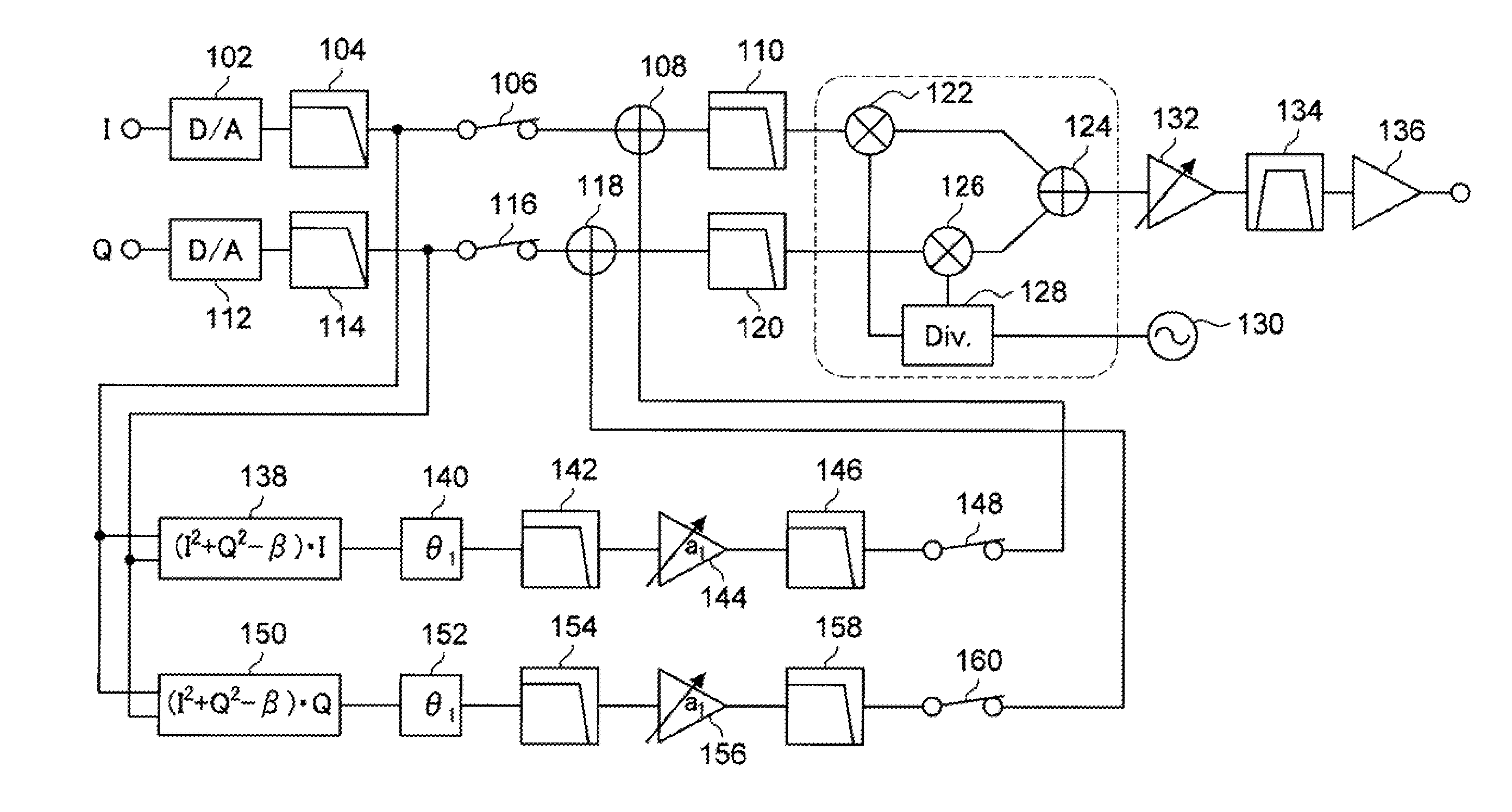
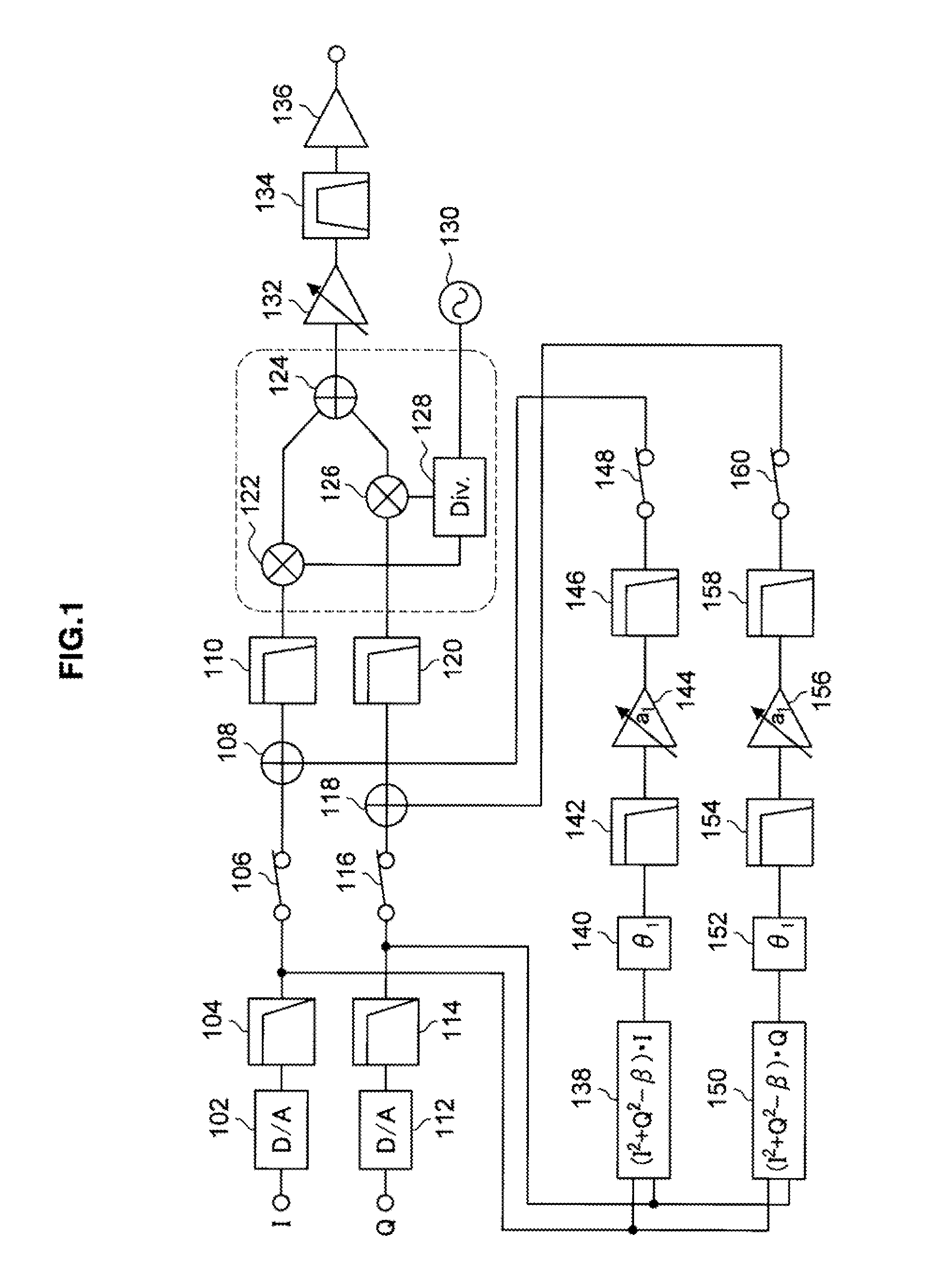
[0089] The distortion compensator achieved in the first embodiment of the present invention is now explained. FIG. 1 is a block diagram showing the functional blocks constituting the distortion compensator in the first embodiment. In the distortion compensator achieved in the first embodiment, a digital orthogonal baseband signal (an I-component and a Q-component) having undergone quadrature modulation in a digital part then undergoes distortion compensation in an analog part by adopting a predistortion technique. In addition, the structure adopted in the distortion compensator in the first embodiment allows a decision is made as to whether or not a predistortion signal (or a distortion component orthogonal baseband signal) to be generated or whether or not the signal is to be used in signal synthesis based upon the output signal level or the like.

[0090] The digital orthogonal baseband signal (a digital I-component and a digital Q-component) signal having un...

second embodiment

of the Present Invention

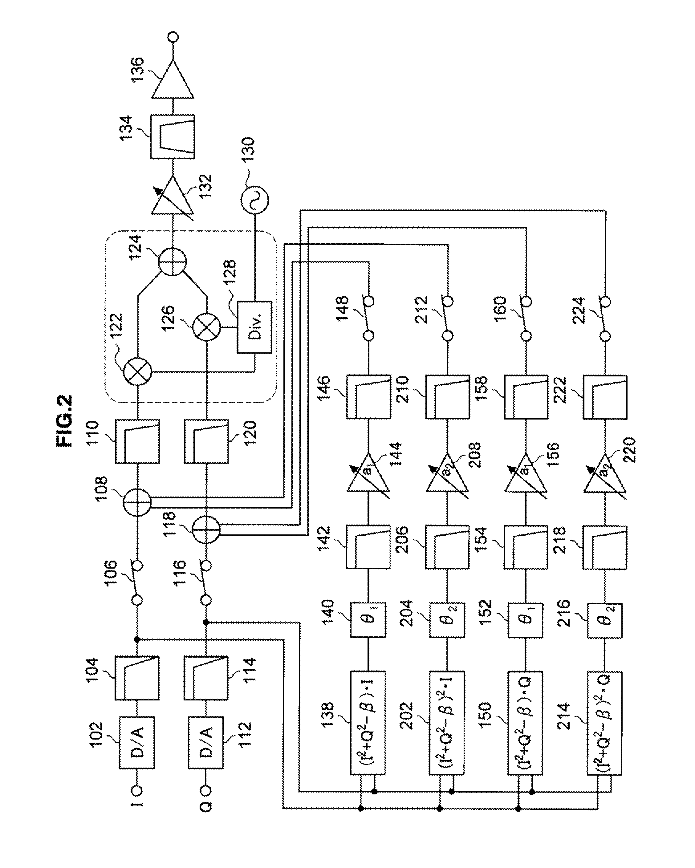
[0129] The distortion compensator achieved in the second embodiment of the present invention is now explained. The same reference numerals are assigned to structural elements identical to those in the distortion compensator in the first embodiment explained earlier so as to preclude the necessity for a repeated explanation thereof and the following detailed explanation focuses on structural elements unique to the second embodiment. FIG. 2 is a block diagram showing the functional blocks constituting the distortion compensator in the second embodiment.

[0130] A structural example of a distortion compensator capable of compensating the third-order distortion component is explained in reference to the first embodiment. The second embodiment to be explained here, on the other hand, represents a structural example of a distortion compensator capable of compensating the fifth-order distortion component in addition to the third-order distortion component. Accordingl...

third embodiment

of the Present Invention

[0156] The distortion compensator achieved in the third embodiment of the present invention is now explained. The same reference numerals are assigned to structural elements identical to those in the distortion compensator in the first embodiment explained earlier so as to preclude the necessity for a repeated explanation thereof and the following detailed explanation focuses on structural elements unique to the third embodiment. FIG. 3 is a block diagram of the distortion compensator achieved in the third embodiment.

[0157] The distortion compensator achieved in the first embodiment includes the switches 148 and 160 through which the predistortion signal input control is executed. In addition, the distortion compensator achieved in the first embodiment includes the switches 106 and 116 through which the analog orthogonal baseband signal input control is executed and thus, allows the output signals obtained by executing power amplification of the predistortio...


PUM


Abstract

A distortion compensator, comprising a distortion component generator that generates a distortion component orthogonal baseband signal corresponding to a nonlinear distortion component based upon an analog orthogonal baseband signal, a distortion component synthesizer that synthesizes a composite signal by combining the analog orthogonal baseband signal and the distortion component orthogonal baseband signal and a first switch through which control is executed as to whether or not to input the distortion component orthogonal baseband signal to the distortion component synthesizer, is provided.

Description

CROSS REFERENCES TO RELATED APPLICATIONS [0001] The present invention contains subject matter related to Japanese Patent Application JP 2006-190073 filed in the Japan Patent Office on Jul. 11, 2006, the entire contents of which are incorporated herein by reference.BACKGROUND OF THE INVENTION [0002] 1. Field of the Invention [0003] The present invention relates to a distortion compensator and a wireless communication device. [0004] 2. Description of the Related Art [0005] An amplifier included in a wireless communication device in the related art tends to generate a distortion component in a carrier when it amplifies the transmission power of the carrier. Such a distortion component may cause a disturbance in the reception frequency band of a cellular phone or cause interference from an adjacent channel such as television or the like. For this reason, it is desirable that a power amplifier achieve low-distortion properties, which do not readily allow a distortion component in the car...

Claims


Application Information

Patent Timeline
IPC IPC(8): H03F1/26
CPCH03F1/3294H03F3/24Y02B60/50H04L27/367H03F2200/336H04B1/10H04B1/12H04B1/14
Inventor TSUDA, SHINICHIROMIZUSAWA, NISHIKIITAGAKI, TOMOARI
Owner SONY CORP
Why Eureka
Try Eureka