Transflective liquid crystal display panel

a liquid crystal display panel and reflector technology, applied in non-linear optics, instruments, optics, etc., can solve the problems of inability to rework the color filter layer on the array substrate, difficult process for removing the color filter layer from the array substrate, and light leakage phenomenon, so as to increase the intensity of reflected light and the reflectivity of the display panel. , the effect of reducing the misalignment between two substrates

Active Publication Date: 2008-02-07
AU OPTRONICS CORP
View PDF4 Cites 5 Cited by
  • Summary
  • Abstract
  • Description
  • Claims
  • Application Information

AI Technical Summary

Benefits of technology

[0012]Preferably, the fabrication of the color filter layer is completed before the fabrication for the thin film transistors. By performing the fabrication according to this order, the color filter can be reworked directly without affecting other devices. Additionally, by integrating both the color filter layer and the thin film transistor on a sub...

Problems solved by technology

If a shift occurs between the two substrates, a color representing a pixel region of the display panel is likely to be influenced by the color of the adjacent pixel region and result in a color-mixing phenomenon, which may further bring a light leakage phenomenon.
However, those skilled in the art would know, if the color filter layer disposed on the array substrate produces any defects...

Method used


Image

  • Transflective liquid crystal display panel
  • Transflective liquid crystal display panel
  • Transflective liquid crystal display panel

Examples


first embodiment

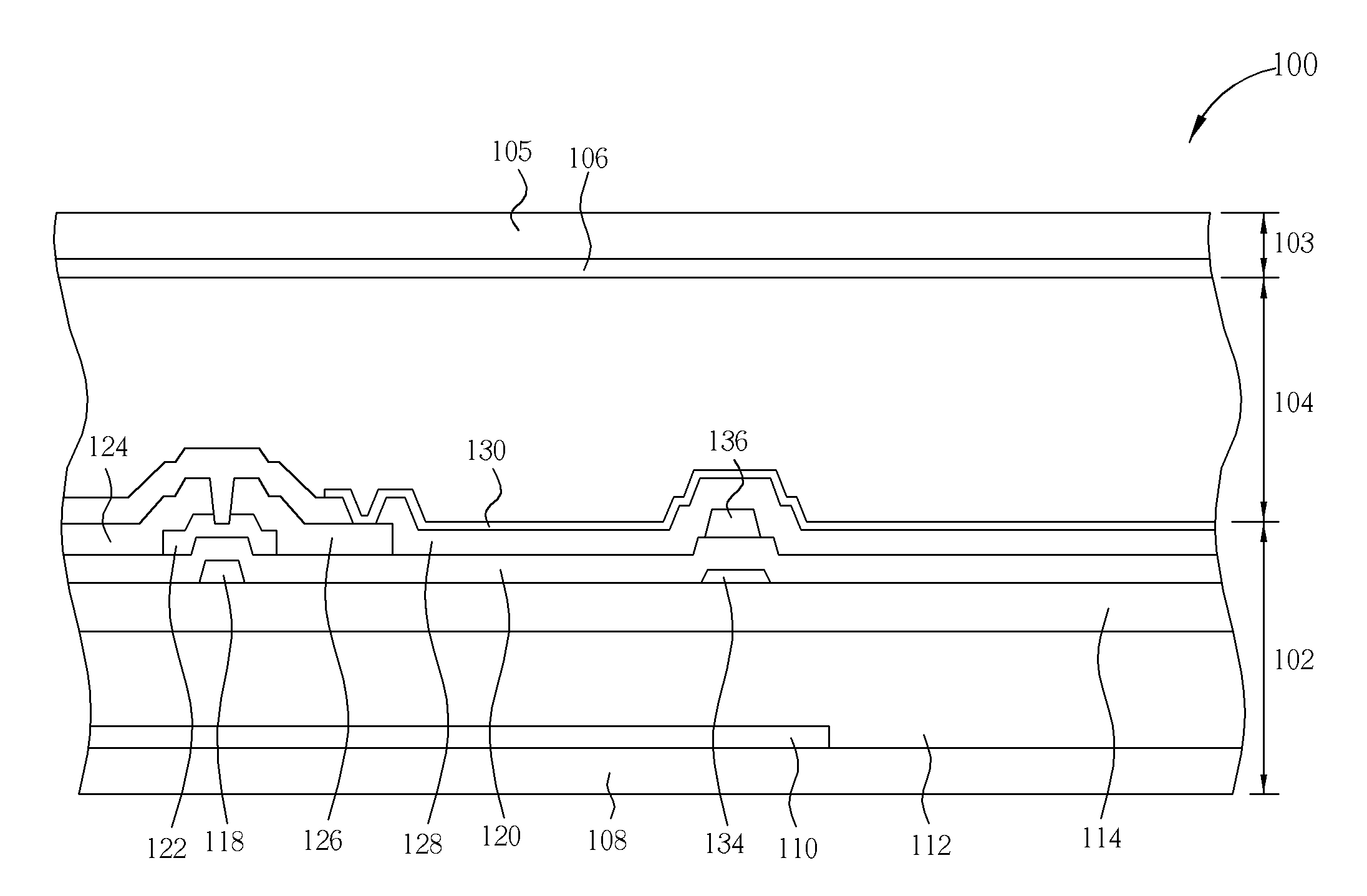
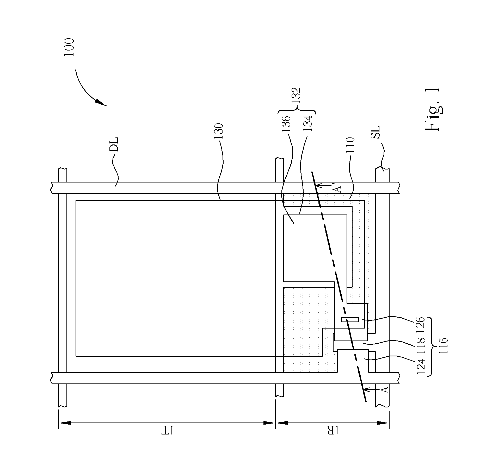
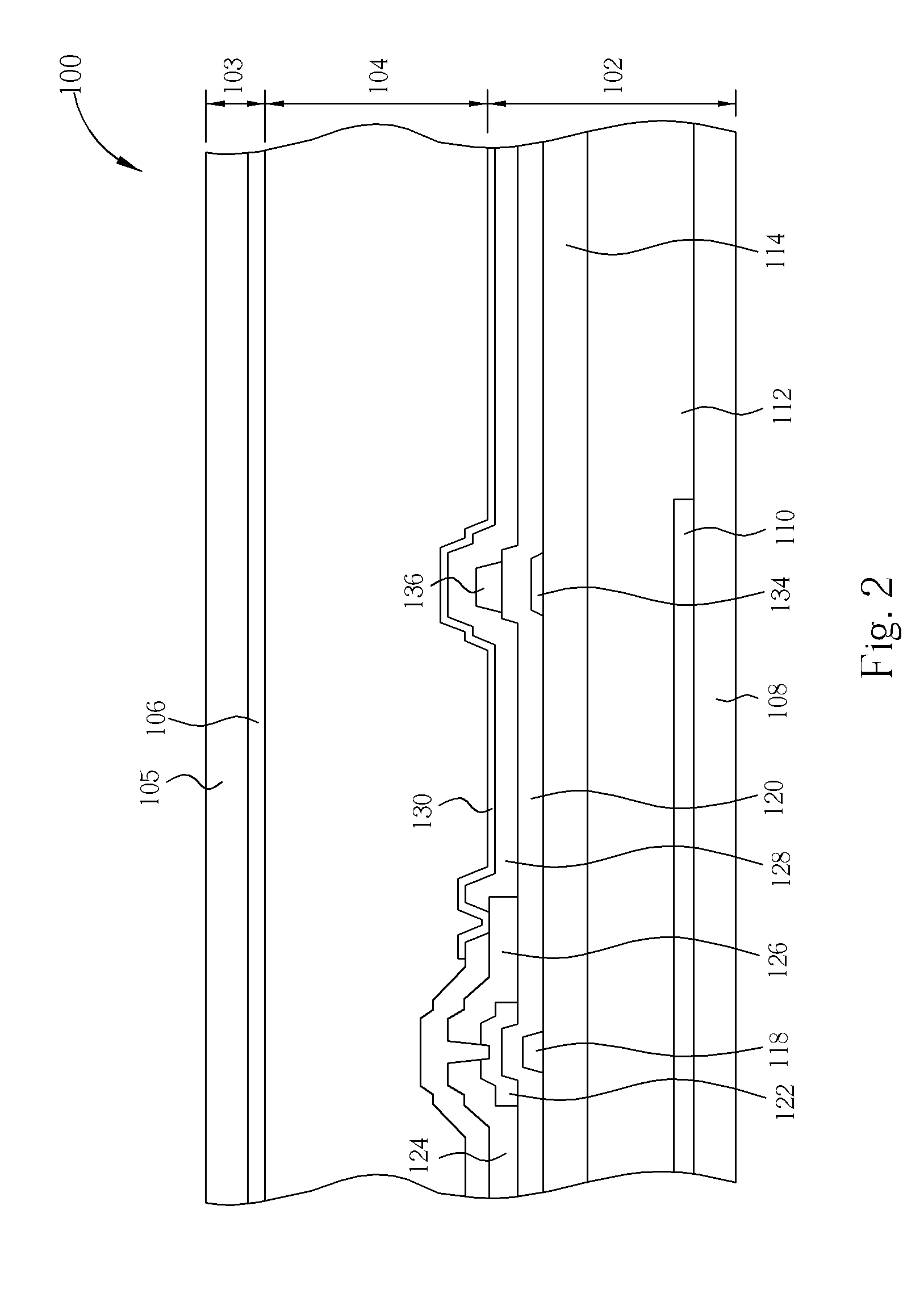
[0026]Referring to FIG. 1 and FIG. 2. FIG. 1 illustrates a top-view of a pixel 100 of a transflective liquid crystal display panel according to the first embodiment of the present invention. FIG. 2 illustrates a cross-section along the line A-A′ shown in FIG. 1. The pixel 100 includes a bottom substrate 102 (such as first substrate), a top substrate 103 (such as second substrate), and a liquid crystal layer 104. The top substrate 103 includes a transparent substrate 105 and a common electrode 106, in which the top substrate 103 can be a vertical alignment liquid crystal display panel or a multi-domain vertical alignment liquid crystal display (MVA-LCD) panel. Instead of disposing on the transparent substrate 105, the common electrode 106 can also be disposed on the bottom substrate 102 to form an in-plane switching liquid crystal display (IPS-LCD). The bottom substrate 102 includes a transparent substrate 108 and a color filter layer 112 disposed on the transparent substrate 108. A ...

second embodiment

[0030]FIG. 3 illustrates a pixel 300 of a transflective liquid crystal display panel according to the second embodiment of the present invention. The second embodiment is structurally similar to the first embodiment described above. However, in this embodiment, the first reflective layer 310 is not only disposed below the interval between the scan line SL and the pixel electrode 130, but also below the interval between the data line DL and the pixel electrode 130 for reflecting ambient light. Additionally, the first reflective layer 310 can also be disposed either below the interval between the scan line and the pixel electrode 130 or below the interval between the data line and the pixel electrode 130. In other words, the first reflective layer 310 is disposed below at least one of the interval between the scan line SL and the pixel electrode 130, and the interval between the data line DL and the pixel electrode 130.

[0031]In this embodiment, a first reflective layer 310 is disposed...

third embodiment

[0032]FIG. 4 illustrates a cross-section of a pixel 400 of a transflective liquid crystal display panel according to the third embodiment of the present invention. The third embodiment is structurally similar to the first embodiment. However, in this embodiment, the first reflective layer 410 includes a rough and uneven surface, such as a waved surface, such that the waved surface increases the reflectance of ambient lights and enhances the uniformity of light distribution. Preferably, the fabrication of the waved surface of the first reflective layer 410 can be achieved by first forming an insulating layer 402 between the transparent substrate 108 and the color filter layer 112. Thereafter, a series of exposure, development, and etching process is performed to form a waved surface on a portion of the insulating layer 402 surface, and the first reflective layer 410 is disposed on the waved surface of the insulating layer 402. Alternatively, a series of exposure, development, and etc...


PUM


Abstract

A transflective liquid crystal display panel includes a first substrate, a second substrate arranged opposite to the first substrate, and a plurality of pixels positioned between the first substrate and the second substrate. Each of the pixels having at least one reflecting region and at least one transmitting region includes a color filter layer formed on the substrate and located in both of the reflecting region and the transmitting region, at least one first reflective layer formed between the color filter layer and the substrate and located in the reflecting region, at least one switch element located in the reflecting region, and at least one second reflective layer located in the reflecting region.

Description

BACKGROUND OF THE INVENTION[0001]1. Field of the Invention[0002]The invention relates to a transflective liquid crystal display panel, and more particularly, to a transflective liquid crystal display panel having integrated switch element and color filter layer on a substrate.[0003]2. Description of the Prior Art[0004]Liquid crystal displays are commonly utilized in various electronic products including personal computers, digital cameras, cell phones, PDAs, and projectors. As the market demand for display panels continues to increase, transflective liquid crystal displays having dual operating modes have become widely popular. Typically, a transflective liquid crystal display includes two operating modes: a reflective mode and a transmitting mode. In most circumstances, when the reflective mode is operating, light from the external environment is being used, whereas when the transmitting mode is operating, light generated from a backlight module is being used.[0005]Typically, a tra...

Claims


Application Information

Patent Timeline
IPC IPC(8): G02F1/1335
CPCG02F1/133512G02F1/133514G02F2201/48G02F1/136213G02F2001/136222G02F1/133555G02F1/136222
Inventor HU, CHIH-JEN
Owner AU OPTRONICS CORP
Why Eureka
Try Eureka